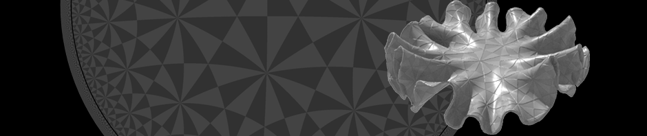
In this first tutorial we build a simple network to visualize Möbius transformations of a given geometry—below a picture of a cube together with its Möbius transform.
![]()
The Möbius transformations are the group of transformations of \(\mathbb R^n\cup\{\infty\} \cong \mathbb S^n\) generated by the Euclidean transformations (rotations + translation) together with inflections in spheres: The inflection in the sphere of radius \(r>0\) with center \(m=0\) is given by\[x\mapsto r^2 \frac{x}{|x|^2}\,.\]In particular, the group contains scalings. Though these maps distort the lengths, they still preserve angles.
![]()
While there are a lot of angle preserving maps mapping \(\mathbb R^2\) to itself (holomorphic maps away from critical points), Liouville’s theorem tells us that in dimension \(n>2\) conformal transformations are Möbius transformations.
On the picture above one can get the impression that the side and edges of the cube are bent to spherical squares and circle arcs. In fact, this is true: Möbius transformations map generalized spheres to generalized spheres. Where a generalized sphere refers to a spheres or a plane—a sphere of infinite radius.
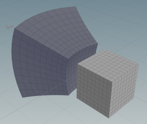
To get a feeling what an inflection in a sphere does, we set up a simple network. We start with an embedded cube \(f\colon \mathbb S^2 \to \mathbb R^3\) and post-compose it with an inflection in a given sphere\(g\) to obtain a new embedding\[\tilde f = g\circ f\,.\]
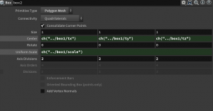
In Houdini this means we generate a cube, e.g. using a box node (make sure that its parameter primitive type is set to ‘polygon mesh’), and modify then its point positions (the point attribute v@P) by a Möbius transformation using a point wrangle node.
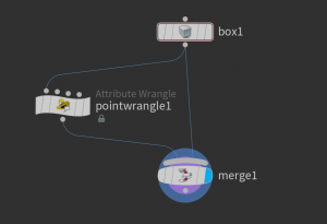
To see both the original cube and the transformed cube we can use a merge node, which merges the two geometries in just one. The VEX code in point wrangle node which does the inversion in the unit sphere is very minimalistic. It just contains one line:
v@P /= length2(v@P);
If you now drag around the original cube you can see how the transformed cube changes. Though the transformed cube still has planar faces and not—as it should have—spherical ones. This is due to the coarse resolution. To obtain a better approximation we need to subdivide the original cube—this can be done directly by setting parameters (‘axis divisions’) of the box node.
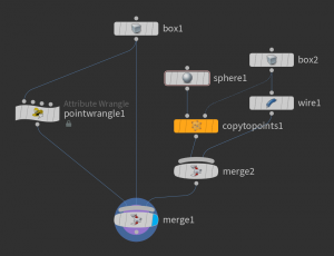
Let us decorate the edges and vertices of the (not subdivided) cube. Therefore we use a wireframe node to paint tubes around its edges and a copy to points node to put spheres to its 8 vertices.
To have both a cube and a subdivided and we set a second box node with center and scale copied from the box1. This can be done by writing ch("../box1/scale") into the Uniform Scale parameter of the second box node box2. Similarly with the center parameter.
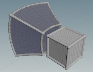
Similarly we can decorate the transformed cube . Only here we need to subdivide the edges so to see that they form circle arcs—this can be done by wiring a resample node as shown below.
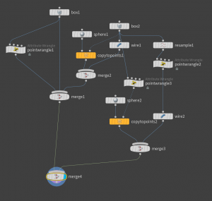
The nodes pointwrangle2 and pointwrangle3 in the network are just copies of pointwrangle1. Here is how the result should look like.
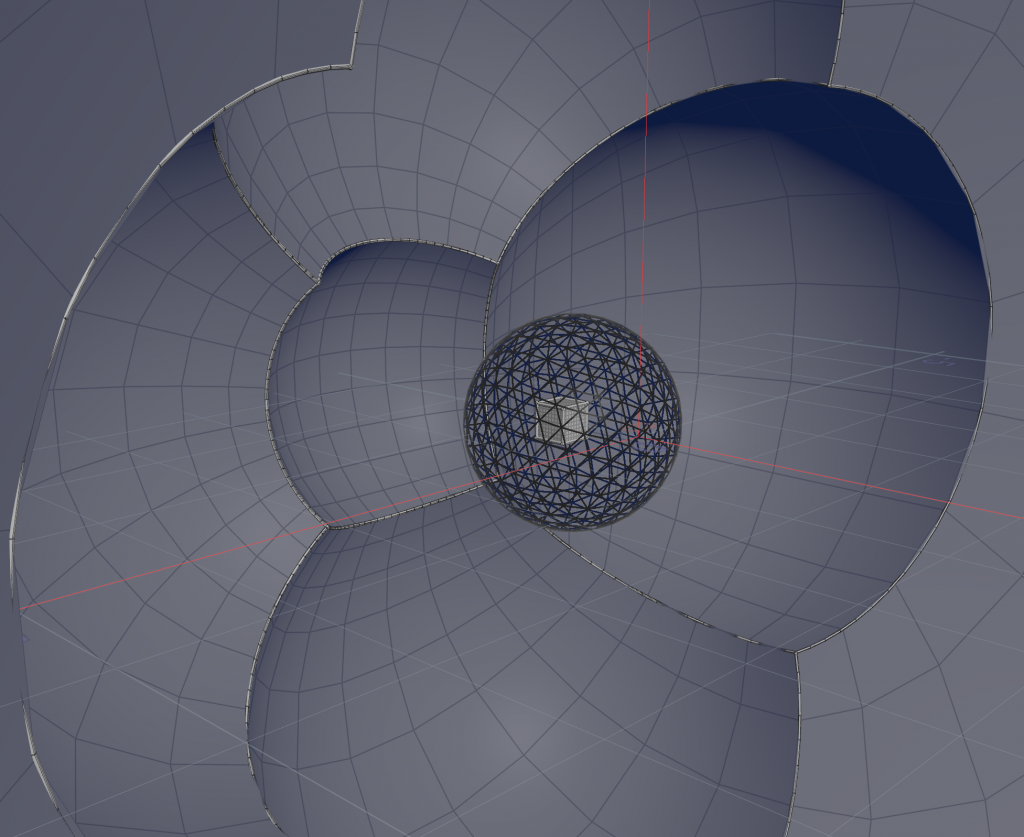
For the inflection we just used the unit sphere. Certainly, it is good to have the sphere also visible in the scene. Therefore we just place a sphere node and merge its geometry to the cube geometries. If one chooses the sphere to be a mesh one can set the f@Alpha point attribute (responsible for opacity) to e.g. 0.1 so that we have a transparent sphere. This is done again by a point wrangle node.
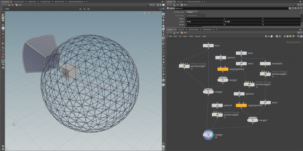
Moreover, given a sphere as explicit draggable geometry we want to make the inflection dependent on this geometry. To do this we access the parameters of the sphere node inside the point wrangle node that performs the Möbius transformation by the VEX function chf (see also this post;).
float r = chf("../sphere3/scale");
float tx = chf("../sphere3/tx");
float ty = chf("../sphere3/ty");
float tz = chf("../sphere3/tz");
In general, Möbius transformations can lead to large length distortion—the whole geometry can sometimes ‘swap over infinity’.
Thus it sometimes might be more convenient to use two sphere inflections instead. So one can easily make a setup such that the cube is contained in one and its transform is contained in the other sphere, as show in the teaser image.
Homework (due 23 April): Build up a network that visualizes the a cube and its inversion in a given sphere, as described above. In particular, make the transform dependent on the center and the radius of the sphere.