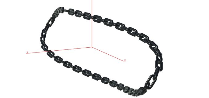
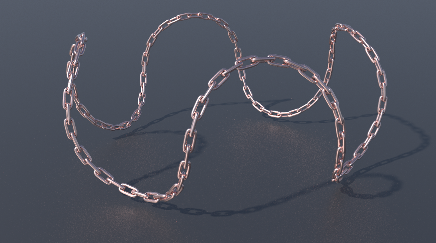
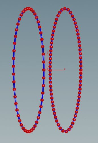
This tutorial will be dedicated to the use of attributes within VEX code inside the example of curves. The goal will be to use attributes in order to create a metal chain effect on the path of a given curve such as in the image below.
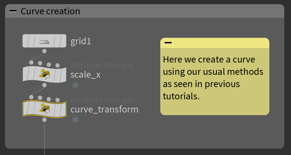
Getting a Suitable Curve
At the beginning we need a curve. This is the code we will want to use. It is nothing new compared to previous tutorials on curves.
|
1 2 3 4 |
// scale X to [0,1] + animation float F = @Frame; float t = F/360; @P.x = @P.x+0.5+t; |
|
1 2 3 4 5 6 7 8 |
// long wiggly ellipse transformation float phi = @P.x*2*$PI; float a = 1; float b = 4; float x = a*cos(phi); float y = b*sin(phi); float z = sin(phi*3+1)*0.3; @P.x =x; @P.y=y; @P.z=z; |
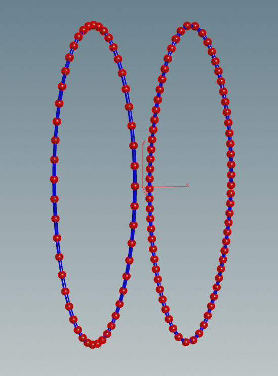
If the curve is visualised with spheres you will notice how the spheres are unevenly spaced. That would be a problem in out implementation of the chains, which is why we will insert a resample node to sample evenly spaced points on the curve. This way we avoid calculating an arc length parametrization. This is the common standard to have parametrization independent curves.

Working with Attributes to Establish Chain Twists
Next we want to put one piece of the chain on each each point of the curve. We had already created the single piece of the chain in the previous tutorial on geometry manipulation.

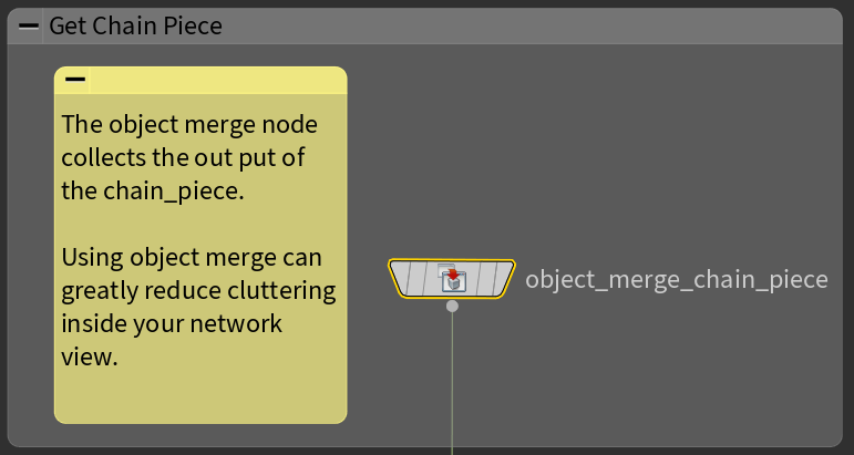
This is a good moment to use the object merge node for the first time. This node allows you to continue with the output of another node without having to connect a line from it in the network view. At the moment we have the chain curve and the chain piece assigned to different geometries in the root level of the network view.

So how to we work with the chain_piece node output inside the chain_curve? Instead of making a copy it is easier to make the object merge node reference our chain_piece node.

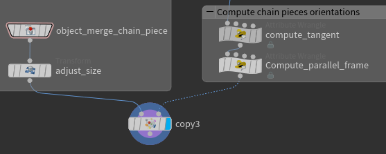
To make the curve look like a chain we need to orient each chain piece along its tangen line and rotate each one as such that every follow up piece is roughly 90° twisted to its predecessor along a specific axis. This extra information for each piece can be written inside the points of the curve using attributes.
We need two more point wranglers to do this. The details of what we are doing inside the code require a wide mathematical theory which is outside of the scope of these tutorials.

|
1 2 3 4 5 6 7 8 9 10 11 12 13 14 15 |
// compute tangents at each point // grab the next point by walking on the half Edge int halfEdge = pointhedge(0,@ptnum); vector nextP = attrib(0,'point','P',hedge_dstpoint(0,halfEdge)); // get edge Vector vector edgeVector = nextP-@P; // expection for end point if (halfEdge==-1){edgeVector={0,0,0};} // create attributes f@pscale = length(edgeVector); v@tangent = normalize(edgeVector); p@orient; // this vector4 quaternion will be specified in the next node. |
|
1 2 3 4 5 6 7 8 9 10 11 12 13 14 15 16 17 18 19 20 21 22 23 24 25 26 27 28 29 30 31 32 33 34 35 36 37 38 39 40 41 42 43 44 45 46 47 48 |
// compute parallel frame node // include math.h is only for using PI #include "math.h" // get number of points in the input geometry int n = npoints(0); // first point orientation is arbitrary vector xaxis = {1,0,0}; vector tangent = attrib(0,"point","tangent",0); vector rotaxis = normalize(cross(xaxis,tangent)); float rotangle = acos(dot(xaxis,tangent)); vector4 orientQ = quaternion(rotangle,rotaxis); // save orientation in the point for the copy node setpointattrib(geoself(),"orient",0,orientQ); // parallel transport int currPoint = 0; vector4 cumQ=orientQ; // total rotation do{ // for every next point, rotate a little more // grab next point int halfEdge = pointhedge(0,currPoint); int nextPoint = hedge_dstpoint(0,halfEdge); if (nextPoint==-1){break;}// end point // get tangents vector currTan = attrib(0,"point","tangent",currPoint); vector nextTan = attrib(0,"point","tangent",nextPoint); // prepare rotation rotaxis = normalize(cross(currTan,nextTan)); rotangle = acos(dot(currTan,nextTan)); orientQ = quaternion(rotangle,rotaxis); cumQ = qmultiply(orientQ,cumQ); // optional: additional twist by PI/2 for interlocking rings on closed curves vector4 R = quaternion(PI/2,nextTan); cumQ = qmultiply(R,cumQ); // store result setpointattrib(geoself(),"orient",nextPoint,cumQ); // advance one point in the loop currPoint = nextPoint; }while(currPoint!=0); |
Note how the compute tangent node introduced the float attribute named pscale by writing f@pscale = . . . ;. Similarly a 3D vector was created using v@, and a 4D vector through p@. All available types can be found here.
The line in the compute parallel frame node shows how to access the attributes from other points using attrib(0,”point”,”tangent”,0); and also how to set attributes by setpointattrib(geoself(),”orient”,nextPoint,cumQ);.
Placing the Chain
Finally we can place our chain links using the copy node. Use a transform node to adjust the sizes of the links and the number of points in the resample node to have a pretty chain. The copy node uses the @orient for the orientation of the copies by default as seen on this link.
The result should be a chain traced along the path of the curve as seen below in render view. The parts of the curve with strong curvature require smaller chain links to look good.