Tutorial: End of year remarks

Today’s tutorial meeting was the last of the year.  Befitting this memorable occasion, we celebrated with punch and cake after taking care of the business at hand:

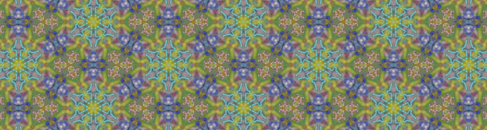
Christmas decorations via the 3D printer.  This meeting had been advertised in advance as an opportunity to play around with making a 3D print.  Since Christmas is around the corner, and we have been studying point symmetry groups, I had suggested as theme making a decoration using the framework of Assignment 6.

In preparing for the tutorial I checked in a new class, util.ThickenSurfaceDemo.  This class takes a surface and thickens it and optionally perforates it (puts a hole in the middle of each thickened polygon).  In order to work with discrete groups, I had to also add a menu item to the jReality export menu, to output a single IndexedFaceSet representing the tessellated geometry.  I managed to to do this also, but the results were not satisfactory.  The thicken step uses the vertex normal direction to thicken the surface and something was wrong the in the geometry which was being written out.  I’ve now found and corrected that bug.  So, if you have created an interesting spherical tessellation which you’d like to print on the 3D printer, here’s what you need to do:

  1. In the program in which you generate the tessellation (for example, Assignment6) save the scene with the File->Export->OBJ menu option.
  2. Start up the program util.ThickenSurfaceDemoLoad the file you created in the previous step using the menu item File->Examples->Load…
  3. Play with the parameters provided until you are satisfied.  Then to save the result for printing in the 3D Lab, use the menu item File->Export->VRML.  In the dialog box, choose the vrml2 option, and uncheck on the other check boxes.  Also save a screen-shot of the result (File->Export->Screenshot) and send it to me as an e-mail.

Note: Due to network problems with my laptop, the changes I have made won’t be checked into the SVN for a few hours (It’s now Thursday 2 pm).

Project presentation planning.  We also discussed the scheduling for giving project presentations at the end of the semester.  Different possibilities were discussed: either directly after the end of the winter semester (in the last week of the semester or the week immediately following), or before the beginning of the spring semester.  This begins on April 7.  I will not be available before April 7.  So this would involve making presentations in the first week of summer semester.  Please consider which of these alternatives you prefer and be prepared to discuss them in our first meeting after we return from the Christmas holidays.

Tutorial: Choosing a project

Please remember that your team should submit a short description of your planned project to me via email by Tuesday 11.12.12. This description should clearly state not only the content of the project, but also what form the project will take.  It is expected that every team will produce either an interactive application or animations in digital format.  These products should include documentation for the intended user/audience. In no particular order, here are some ideas for semester projects.

  1. Dynamical systems on orbifolds.  This is a big field, with many possible specific projects. Idea is to take some dynamical system defined on $\mathbb{R}^2$ (or $\mathbb{R}^3$ or $\mathbf{S}^2$ or $\mathbf{H}^2$ or …) and figure out how to map it onto some or any orbifold that belongs to this covering space.  Example: vector fields , differential equations, difference equations, cellular automata (as in Assignment1).  (To see how to integrate ODE’s in Java, see the example util.ODEExample.)
  2. Complex functions.   There are doubly-periodic complex functions, aka elliptic functions.   These can be considered functions on the torus.  Interpret them for example as vector fields, calculate the integral curves.
  3. Geometry processing on orbifolds.  For example, develop software to work with triangulations of an orbifold.  How to insert new points, how to perform geometric processing on the resulting triangulations.  Calculate subdivision surfaces in 2D- and 3D-orbifolds.  Develop tools to study embeddings of graphs on tori and higher-genus surfaces.
  4. Software improvement. Improve or extend an existing application such as TriangleGroup, Wallpaper, Maniview.  For example:
    1. Provide a geometric representation for 3D isometries so that one can provide a picture of the generators of the discrete group. This has been begun in the euclidean case (in maniview) but not completed.
    2. Better painting tool. The painting tool in the wallpaper application could be better. It would be nice for example to fair the input path of the mouse — this means approximate the path with a Bezier curve, as the user draws.  This will provide a more uniform, smoother curve, which is also easier to store off and later edit.  (Of course the user can choose whether he wants to fair or not.)
  5. Software applications. Here are some ideas for self-contained applications.
    1. 3D Kaleidoscope. Implement a general 3D Kaleidoscope in the sides of an appropriate 3D tetrahedron (one with dihedral angles which are fractions of 2Pi).  Equip this kaleidoscope with a set of built-in “worlds”, each of which generates its own regular 3D tessellation.  For example, with the same *236 kaleidoscope it’s possible to generate tessellations consisting of regular hexagons, regular triangles, or a combination of both.  Figure out how to design these worlds so that you can see through them to perceive the complete tessellation. This idea is the analogy in 3D to the TriangleGroup webstart in 2D.
    2. Designing large public sculptures with spherical symmetry.  Here the model is George Hart’s construction projects based on a single tile, typically working with the symmetry group 235.  The project here would consist of an application to allow the user to design a single tile (piece of cardboard or plywood) which is so designed that it can be easily attached to other copies either via gluing tabs or thin slots.  Given a suggest shape, the application should allow the user to move, scale and rotate it into place; and additionally provide some support for editing it in a 2D editor and updating the complete 3D sculpture in a separate window.
    3. Brick patterns. Develop a module for the wallpaper application (above) devoted to symmetry patterns based on bricks (rectangles with 2:1 aspect ratio).  See the book by Peter Stephens, Regular Patterns, (in the math library “Semesterapparat”) for examples of such patterns.  This brings one to the topic of tilings, which we haven’t explicitly studied.  There may be several distinct tilings which all have the same symmetry group.  See the web page of Craig Kaplan for more on tilings.
    4. Color symmetry.  Using the book The Symmetry of Things (see below) as a guide, write an application to explore color symmetry in wallpaper groups.
  6. Implement some of the missing 3D Euclidean crystallographic groups, for example, debug the 35 irreducible ones, or begin to work on the fibered ones.  References here: original paper by Thurston, Conway, Huson, and Delgado and these slides from a talk by Huson.
  7. Content. It’s also conceivable to author content rather than software or mathematics.  That is, choose a theme and develop material to communicate this theme to others.  Here the focus is not on innovation in mathematics or software, but communication.  Think “movie” — without expecting the production of a finished movie (that’s too much work). Examples of possible themes:
    1. An interesting set of animated tessellations would fall into this category
    2.  a gallery of classical patterns from various cultures (see the book by Stephens references in 5)).
    3. The 59 stellations of the icosahedron.
    4. “The 120 Cell”
  8. For more ideas about symmetry-related project themes, see the following resources:
    1. Craig Kaplan’s web site
    2. George Hart’s web site.
    3. Vi Hart’s YouTube videos, for example this one.
    4. The book The Symmetry of Things by John Conway  (in Semesterapparat).
    5. The book Regular Patterns by Peter Stevens (in Semesterapparat).

New for 2013

  1. Tools for visualizing projective geometry.  There have been surprisingly few attempts to develop tools for visualizing projective geometry in dimensions 2 and 3.  The mathematical foundation is clear and rich, the jReality system provides excellent support for the homogeneous coordinates and projective transformations.  What remains to do is develop some ideas for how one can specify and render geometry and projectivities in a clear, intuitive fashion. For example, “the line segment AB” is not well-defined, one must distinguish somehow between the two possibilities.
    1. One simple test case for the 2D case is the “guided visualization” we have been practicing in class in which 4 triangular regions change their appearance as one of the intersections points passes through the ideal line.
    2. Another direction for work would  be to explore how far one can go in using projective transformations to represent deformations of euclidean objects — that is, take Assignment1 extra credit option and “run with it”.
    3. Another related application: one that allows the user to specify a 3D projective transformation by picking 5 points, and then applying it to a grid of cubes (or some other regular euclidean pattern) to obtain a linear deformation of this pattern.

Lecture notes: 03.12.12 Bezier curves

I introduced Bezier curves and surfaces yesterday with a quick and non-technical treatment focusing on the recursive definition of the Bezier curve of order $k$ as a weighted sum of two Bezier curves of order $k-1$; the recursion is rooted in the definition that order-1 Bezier curves are line segments linearly interpolated between a pair of control points:

\[ \beta(P_0, P_1; t) := (1-t)P_1 + tP_2 \]

The definition of order-2 (quadratic) Bezier curve is then

\[\beta(P_0, P_1, P_2; t) := (1-t)\beta(P_0,P_1,t) + t\beta(P_1, P_2, t) \]

In general, one arrives at a polynomial expression in terms of the control points $P_i$ which is given for the order-n case by:

\[ \sum_{k=0}^n B_k^n(t) P_k \]

where $B_k^n(t)$ is the Bernstein polynomial defined by $B_k^n(t) := \binom{n}{k}(1-t)^kt^{n-k}$. Using this form it is not difficult to prove many attractive properties of the Bezier curves, such as: the tangent direction at $P_0$ is in the direction of $P_1$, etc.

To help you visualize the recursive definition of Bezier curves, I’ve created a demo in the SVN repository for our class. Update and run the main() method in util.BezierDemo. You’ll need to invoke the animation panel and set two key frames (by clicking on Save then Insert buttons), then hit the play button.  You’ll probably want to adjust the playback speed also.  Here’s a movie showing the result:

Rational Bezier curves.  If one uses homogeneous coordinates for the points of space, then one can generate a wider variety of curves using the same algorithm.  Remember, the final step of drawing the curve is to dehomogenize, that is, divide by the homogeneous coordinate, which in our case is the $w$-coordinate. Such a curve is then a rational rather than a polynomial curve.

Representation of circles. In particular, it is possible to parametrize arcs of circles using rational Bezier curves of degree 2.  This takes advantage of the fact that the circle an be represented rationally as the homogeneous curve $(1-t^2, 2t,1+t^2)$.  For $t\in [0,1]$, this parametrizes the first quadrant of the unit circle.  It turns out that the Bezier curve with control points

\[ P0 := (1,0,1),~~~ P1 := \dfrac{\sqrt{2}}{2}(1,1,1), ~~~P2 := (0,1,1) \]

provides essentially the same parametrization of this circular arc.

Bezier surfaces.  There are two approaches to generalizing the above approach to generate surfaces.  In the first, one begins with a triangle instead of a line segment, and two parameters $u$ and $v$ instead of $t$.  Then the order-1 interpolation of the triangle is defined as

\[\beta(P_0,P_1,P_2; u,v) := (1-u-v)P_0+uP_1+vP_2\]

The other approach creates surfaces as the tensor product of two curves.  In this case, one requires for an order-n surface a total of $(n+1)^2$ control points.  One considers these points arranged in a square array.  Then to create the surface, consider each row of the array as the control points for an order-$n$ Bezier curve.  Use the $u$ parameter to obtain a point on each of these curves.  Then, consider these $n+1$ points as the control points of a Bezier curve, and apply the $v$ parameter to obtain a point on it.  This is the value of the surface at the parameter value $(u,v)$.  It’s not hard to show that one obtains the same result if one begins with the $v$ parameter and then applies the $u$.