Tutorial: Project evaluation criteria

This week focus is the criteria which will be used to evaluate your project work.  Part of the evaluation will be based on the software project itself; the rest will be based on the presentation.  I’ll deal with each of these parts separately.  The assignment for next week is to write a preliminary version of the on-line documentation file for your project, as described in more detail below.  Check this into the SVN repository by Friday, Feb. 1.

Before I get to that, here are some organizational details:

  • at tomorrow’s meeting we’ll discuss the contents of this post, with reference to a couple of example applications which I will demo.  I hope to have the pleasure of seeing at least one member of each team tomorrow morning.
  • I will also pass around a sign-up sheet for another round of appointments on Monday and Tuesday of next week (January 28-29) to discuss the progress of your projects individually.
  • Finally, if you intend to present your work in February, please notify me in writing, so that we can get serious about setting up dates for these talks.

Criteria for the software.  Here there should be no big surprises, as the criteria used to evaluate the software have all been introduced during the assignments which you have turned in during the semester.  Here’s the key points.  Pay special attention to the last two, as they are perhaps a bit new, although hopefully not surprising.

  1. The project itself should be a subclass of util.Assignment.
  2. On-line documentation. The project should include a html file as in our assignments (via the method getDocumentationFile()) which includes these three sections, listed below.  Note the I expect you to check in to SVN a preliminary version of this documentation by Friday, Feb. 1!
    1. The mathematical content of your project.  This should first of all “zoom in” to the specific domain of mathematics you are handling. For example, don’t just begin by saying, “We provide an application to identify the symmetry group of a wallpaper pattern”; rather begin by briefly reviewing the theory of symmetry groups on in the euclidean plane, and discuss how the classification of wallpaper groups can be mathematically described.  You should conclude this section with a single sentence describing your application as clearly and precisely as you can.
    2. Following this mathematical introduction, your documentation should then turn to the software implementation. How did you map the mathematical content onto the software platform you used?  Briefly describe the “flow chart” of the application, describing how you have implemented the mathematical content described in the previous section.  Mention any Java classes you have written, and any external packages or classes which play important roles in your implementation.  Indicate areas where you are satisfied with the results you obtain, and also those where you would work further if you were to continue on this project.
    3. User interface.  A description of the user interface of the program, preferably with screen shots showing the GUI (graphical user interface).
  3. User interface. How easy is your application to use?  Have you designed the user interface so that the user can experience the mathematical content in as simple and direct a way as possible? Have you taken advantage of the packages we have used so far in the tutorial (jReality, discretegroup, etc.)?  For example, have you used the appearance capabilities in jReality to help communicate the content of your application (colors, rendering attributes, etc.)?  Are the GUI components clearly labeled and neatly laid out? Does the documentation match the reality?
  4. Saving/restoring state.  One aspect of a successful user experience is the abillity to continue working after restarting the application.  That means, critical parameters should be saved (restored) when the application ends (starts up).  Use the methods  storeStates(Controller c) and restoreStates(Controller c) for this purpose.  I have extended gunn.Assignment2 to use these methods to store/restore its state; consult it to see how to do this for your own application.  These properties are saved off into a special file called the properties file for the application.  To be safe, you should specify a unique properties file for your project.  To see how to do this, look into the display() method of Assignment2, specifically, the JRViewer method setPropertiesFile().  Note that you do not need to specify a path for the properties file  if it is located in the same folder as the Java class of your application.
  5. Commented code.  Your Java code will not be put under a microscope and evaluated. At this stage, it’s more important that it works than how it works.  On the other hand,  I expect a minimal level of documentation in the source files:  Each method in your Java code should have a comment preceding it which describes what it does.

Criteria for Presentation. The talks are limited to 30 minutes.    It should follow the structure described above for the on-line documentation file.  There will be 15 minutes for discussion and questions. The best preparation is to understand and be able to talk about the mathematical content, the programming decisions you made, and how you would proceed if you were to continue with the project further.

Tutorial: Writing jReality tools

Please note the following points from the Tutorial meeting yesterday (Jan. 10):

  • Your project software should be based on a Java class which is a sub-class of util.Assignment.  Please name this class Project{TeamIdentifier}.java.  For example, if I were a singleton team, I’d name my project ProjectGunn.java.  This is a change from the convention we adopted for assignments; I’ve decided it’s worth having unique names when I’m busy testing out the results and don’t want to get confused by a run history featuring 10 applications all named Project.
  • There are at least two teams which prefer to present their results at the end of the semester (meaning either the last week of classes or the week after the last week of classes). If you would like to also present your project in February please contact me to let me know.  All the other teams are then expected to be ready to present their projects during the first week of the summer semester (the week beginning April 8).  This is a hard deadline. Please plan accordingly.
  • A sign-up sheet for appointments for team meetings next Monday and Tuesday was passed around.  If your team wasn’t represented on Thursday at the tutorial, please contact me to arrange a meeting.
  • The rest of the period I discussed the jReality tool system.  Although I promised that there will be no more assignments (your project is THE assignment), I’ve gone ahead and written gunn.Assignment7 for your edification.  It is not an assignment in the traditional sense, since you are not expected to write your own version.  However, I expect you to study it and become familiar with how the tool contained in it works, since most projects involve an interactive aspect which will require that you write your own tools.  The rest of this post describes this application and the jReality tool system.

The problem statement

Up til now, we have concentrated on creating scenes for jReality, learning in the process how to use the class SceneGraphComponent to build a scene graph, Appearance to control how it is rendered, a variety of geometry factories for generating content, and a variety of utility classes for performing common tasks.  We’ve also practiced using some external packages relevant to our mathematical theme:  the discretegroup package for working with symmetry groups, and an animation package for designing and saving animated sequences.

One major area which we haven’t worked with in detail is the jReality tool system.  This s a sub-system which allows the user to interact with the running application using input devices.  This is not the place for an exhaustive treatment. Read this Wiki entry for an introduction to the tool system.

Very short description of the tool system: In order to provide a layer of abstraction between the actual hardware input devices and the tool system (in order to allow the same application to run in different environments such as a desktop and the PORTAL), the tool system is based on the notion of an input slot, which represents some kind of input device.  Slots generate input events; tools inserted into the scene graph are notified of these events depending on the positions of a) the tool in the scene graph and b) the source of the event (also typically in the scene graph).

The basic interactive tool will have some activation slots which cause the methods activate() and deactivate() to be called; while it is active, events arising from its current slots will cause its perform() method to be called.  The tool is provided with an instance of ToolContext, which contains information describing exactly where the scene graph has been picked by the user.  The most important part of the ToolContext are methods which provide the current pick results (getCurrentPick() and getCurrentPicks()), along with methods providing SceneGraphPath’s specifying where the active tool is located, and where the picked geometry is located (getRootToTool() and getRootToLocal()).

Assignment7 embodies a simple curve editor.  The user interacts with the curve via a single tool inserted into the same scene graph component containing the curve.  This virtually guarantees that it will only receive tool events involving this curve, but not for example the square background geometry). There is a single InputSlot, the left button input slot.  When the user presses the left button, the tool is activated, and when he releases it, the tool is deactivated.  If the cursor is over the curve, the activate() method does the following:

  1. If an edge has been picked, (this can be found out by the method PickResult.getPickType()) then the tool inserts a new vertex into the curve at the picked point of the edge, and turns off picking of edges for this geometry.
  2. If a vertex has been picked, the perform() method is called.

The perform() method only takes action when a vertex has been picked.  Since edge picking has been disabled, this should always be the case. It then edits the list of vertices of the curve to move the picked vertex to a new position given by the pick point (note that this is different from the coordinates of the picked vertex, since the coordinates of the pick point correspond to the point on the tiny sphere which is drawn to represent the underlying vertex.  If you want to access the actual coordinates of the picked vertex, you  can use the getIndex() method of the PickResult class to obtain the index in the vertex list of the IndexedLineSet to obtain this information.  The code contains numerous examples of how such methods can be used so I refrain from further “explaining”.

Don’t neglect to update jReality before testing out Assignment7: a small extension had to be made to the PickResult class in order to be able to locate exactly the picked segment along the curve (the method getSecondaryIndex()).

lecture notes: 11.12.12

Let $x,y,z\in\mathbb{R}$ vertices and the “wrap” $g\in\mathrm{G}$ an edge. Then wie have the vertices head and tail and the edges prev and next.
Bild01

component(e)
mark(e);
e' := e;
while(e'≠ e) do
e' := next(e');
if (e' == e) return true;
mark(e');
endwhile
e':=e;
while (e' ≠ NULL) do
e' := prev(e');
if(e'==e) return false;
mark(e');
endwhile

findcomponents()
num_circles :=0;
num_ints :=0;
unmark all edges;
for each edge e do
if (marked(e)) continue;
if (component(e))
then num_circles ++;
else num_ints++;
endif

Data Structure for surfaces

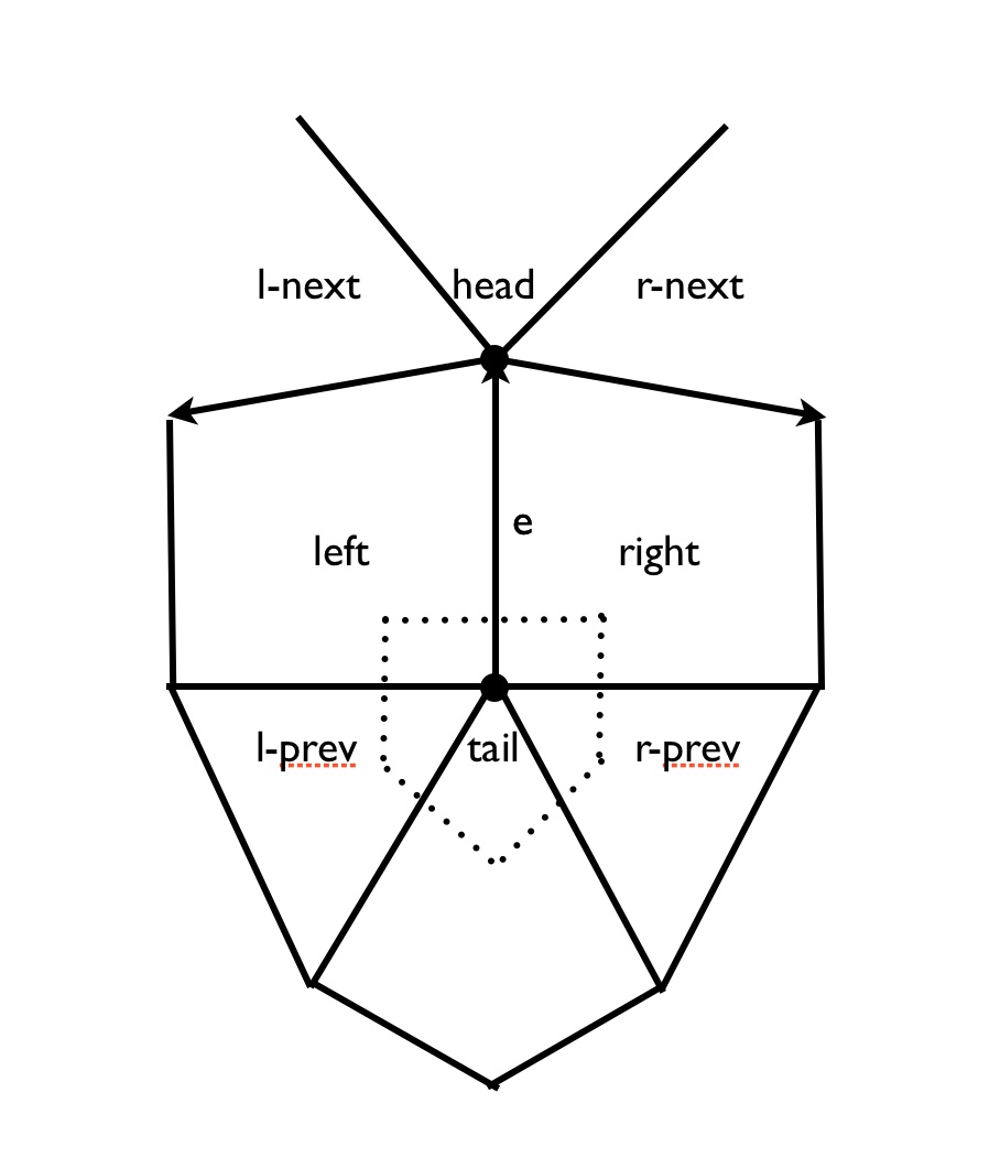
There are winged edges, half edges and quad edges. An oriented edge has the vertices head and tail and the faces left and right.
Bild02
head-next(e) = – r-next(e)
head-prev(e) = – l-next(e)
tail-next(e) = – l-prev(e)
tail-prev(e) = – r-prev(e)

There is a duality: vertex $\leftrightarrow$ face, edge $\leftrightarrow$ edge ($\bot$) and face $\leftrightarrow$ vertex.
Quad edge represents both together, vertex and face are the same data structure (e.g. coordinates of vertex area of dual face). A “quad edge<2 has pointers to four vertices/faces and pointers to four other quad edges.
Store quad edge once. A reference to a quad edge is a pointer to this data structure together with two bits $±e$, $±e^+$. We need enumerators for each edge, vertex and face. and some pointers back from a vertex/face to an incident edge.

mark all edges, faces, vertices
for each edge e do
if unmarked(e)
then find_component(left(e));
end for

find_component(f)
recursively mark all neighbors (breath-first or order-first, pruning when we see a marked face);
As we go, count faces, edges, vertices;

If we pass a marked face again with oposite direction, set a “nonorientability” flag.

Need to count components: $\chi = \mathrm{V}-\mathrm{E}+\mathrm{F}$.
With some modifications quad edges, etc. also work for multigraphs in a surface.

Similarly, for any 2-complex in $\mathbb{R}^3$ or for a 3-manifold given as a 3-complex we can use facet edge data structure.
A facet edge $f_e$ represents one edge of one face in the complex.

next_edge($f_e$), next_facet($f_e$), prev_edge($f_e$), prev_edge($f_e$)

The facet edge has four pointers to $f_e$’s, 2 pointer to vertices (head, tail) and 2 pointers to cells (above, below).
Especially when the complex forms a closed 3-manifold, we can implement duality as quad edge.

lecture notes: 10.12.12

Topic: polygons, polyhedra, cell complexes and data structure for these.

$n$-manifolds looks locally like $\mathbb{E}$. Further a $n$-manifold with boundary has points with neighboorhoods like a halfspace $\{x\in \mathbb{E}^n | x_n\geq 0\}$. Compact manifolds (with boundary) are the ones that can be represented in the computer, say by a finite triangulation.

Definition: A closed $n$-manifold is a compact manifold without boundary.

Each component of a $0$-manifold is a point. The manifold is compact iff it is finite. A connected $1$-manifold is $\bigcirc\cong\mathbb{S}^1, \:\mid\:\cong [0,1],\:\updownarrow \:\cong\mathbb{R}\cong(0,1)$ or $\uparrow \:\cong\mathbb{R}_{\geq 0} \cong [0,1)$. Thus, a compact $1$-manifold has finitely many components, each is $\mathbb{S}$ or $\mathrm{I}$.
Recall: each component of a compact $2$-manifold is $\sum_{g,k}$ if orientable or $\mathrm{N}_{h,k}$ if not.
Represent a compact $1$-manifold by gluing edges together: Start with n edges and some identifications of the end points (an equivalence relation on the set of $2n$ end points). In general this gluing gives a multigraph with $n$ edges and less than $2n$ vertices. The size of each equivalence class is the degree of the resulting vertex. A finite multigraph can be realized this way iff there is no vertex of degree $0$.

Lemma: A multigraph is a $1$-manifold iff every vertex has degree $1$ or $2$.

Definition: The body is exactly the set of all vertices of degree $1$.

For $2$-dimensional manifolds (and cell complexes) we start with a finite collections of polygons and a rule for gluing edges. Equivalently, we can require that all the polygons are triangles.

Definition: An oriented $n$-gon is topologically an oriented closed disk with n marked boundary-points $a_i$ in cyclic order.

The gluing rule is an equivalence relation on the set of all oriented edges with the porperty that $e\sim f \Leftrightarrow -e \sim -f$. The equivalence classes are the oriented edges of the resulting $2$-complex.
The degree or valence of the resulting edfe is the cardinality of the equivalence class. The resulting compact space is a $2$-manifold iff all edges has valence $1$ or $2$ and edges of valence $1$ form the boundary. We get a manifold if we start with pairing of the oriented edges. The manifold is closed (no boundary) if all edges get paired.

The $2$-complex we get is always purely $2$-dimensional (no edges of valence $0$, no isolated vertices). Not every purely $2$-dimensional complex can be obtained by our construction. We’ve given a “top-down” $\:$construction of complexes. Start with to-dimensional cells gluing their face.
The other construction of cell complexes is “bottom up”.$\:$Start with a finite set of vertices. Then sew in a finite collection of edges (to head and tail vertices). Finally sew in $n$-gons by attaching boundary to a cycle of $n$ oriented edges.
With this second construction edge valence is $0$ or $2$ is necessary but not sufficient to get a manifold with boundary. We need to test that the link of each vertex is connected. Assuming the valence conditions, the link of each vertex is a $1$-manifold – we just need to check if it is $\mathrm{I}$ or $\mathbb{S}^1$.
Usually we have geometric information about how a complex is sitting in some ambient space. E.g. each vertex has coordinates. Usually edges are straight lines in the ambient space.
We may need to mark edges to say which “way around”$\:$ in the ambient space they go. If the ambient space is $\mathbb{R}^3/\:\mathrm{G}$ for some crystallographic group $\mathrm{G}$, then we often represent vertices as points $v\in\mathbb{R}^3$. An edge from $v$ to $w$ is marked with $g\in\mathrm{G}$ to show that it is the straight line $v$, $g\cdot w$ is one of the preimages.
Sometimes multiple edges are usefull even if the start in the same position.