Using gitorious.org, Part II

In this followup post to the original posting on this subject, we  deal with how to work with changes in the source code.  There are various sorts of situations we need to handle:

  1. You want to push your work from your local repository to your gitorious repository, either to make it available to your team members, or to turn it in to me.
  2. You need to update your version of my repositories.  This can happen in two ways:
    1. the jReality clone which you used to set up your workspace has  been changed — typically to add a feature or fix a bug which is relevant to our class work.
    2. the course repository has been updated with a new assignment which you need to integrate into your workflow.

The solutions presented below — in contrast to the original post for gitorious — are based on the git command-line interface.  So to use them, you need to have a shell open.  Commands in this shell will be indicated by a leading ‘%’ to indicate a shell prompt.

Preliminary repair work. Before beginning we need to do a little repair work.  Change directory to where your local git repository for the course is, and then change directory into the .git subdirectory.  Use a text editor to edit the file config, to replace any occurrences of the string “assg1” with “master” (this reflects the fact that I have changed the course repository on gitorious to have only a single branch named “master”; having more was just going to be too complicated for everyone).  If you have any questions, wait until the next tutorial meeting to carry this out.

Push your work up to your gitorious repository. The solution to 1. above is simple.

  1. First we give the commands, then we explain them:
    • % cd my_local_git_repository
    • % git add .
    • % git commit -m “My version of Assignment1”
    • % git push
  2. The ‘add’ command adds any files you’ve created to the list of changes to be committed to your local repository.  The ‘commit’ command commits these changes to your local repository.  The ‘push’ command propagates them to your gitorious repository.
  3. If you have your ssh keys properly installed, this should propagate your changes to your gitorious repository.
  4. Now you can notify your team member of the changes, or if the changes represent something that I should see, send me an e-mail notifying me.  Be sure to paste the string for your gitorious repository into the e-mail, so I can install it into my eclipse workspace in case I don’t already have it or identify it (if I have installed it).
  5. If you want to update from your repository (either because you’ve updated it from another computer or a collaborator has done so), use the command
    • % git pull
    • or, in eclipse, “Team->pull”

Update your jreality to the latest version.

  1. Issue the following commands in a shell:
    • % cd my_local_jreality_repository
    • % git status
    • % git checkout origin/develop -b develop
  2. If the last command complains that the branch “develop” already exists, then just omit the “-b develop”.
  3. From now on, to update jReality you can issue the command
    • % git pull
    • or, inside of eclipse, “Team->pull”

Update to the latest version of the course repository tu-mathvis-ws13.

In the course of the semester there will be new assignments that you need to “download” from the course repository.  They do not immediately show up on your cloned gitorious repository.  This is the most complicated procedure since it represents an independent branch of the repository which has to be merged into your working version. Here is how you can update using the git command line.

  1.  Then issue the following commands in a shell:
    • % cd my_local_tu-mathvis-ws13_repository
    • % git status
    • % git remote add teacher git://gitorious.org/tu-mathvis-ws13/tu-mathvis-ws13.git
    • % git fetch teacher
    • % git checkout teacher/master -b teacher
    • % git checkout master
    • % git merge teacher
  2. Explanation: The “status” command should show a “clean” branch — one with no changes that need to be committed.  If there are un-committed changes, commit them first.  The “remote” command adds a new remote reference to your git repository with the name “teacher”.  This is my original repository that you cloned on gitorious. The “fetch” command brings over the current version of this “teacher” repository into your local repository. The first “checkout” command checks out the “master” branch of this “teacher” repository, and creates a new local branch named “teacher” for it.  The second “checkout” command reverts the current working directory to the “master” branch of your local repository.  The “merge” command merges the “teacher” branch into this local “master” branch.  If you have been following the rules for development, then the changes from teacher and the changes you makes should be mutually exclusive and the merge should be trivial.
  3.  You can then commit the changes and push the result onto your gitorious repository following the instructions at the beginning of this document.

15.10 Tutorial: Getting Started with the Tools

Dr. Gunn spent the first 10 minutes setting up the beamer he brought with him, overlooking the beamer installed on the ceiling.  Next time!

Dr. Gunn introduced Benjamin Kutschan, an experienced student who has volunteered to assist with the tutorial. After discussion with students, Dr. Gunn decided to offer the tutorial on both Tuesday 12-14 and Thursday 12-14 in MA 313.  Students should choose one of these two days to attend.  These times will be mostly open consulting times where Dr. Gunn and Benjamin will circulate among the students teams and answer questions, etc.  Please bring your laptops.

Dr. Gunn introduced the jReality web-site.  He showed how to access and experiment with the jReality Developer tutorial:

  • If you have problems with the “Run as Java Webstart” button on the tutorial pages please activate the Java console (on recent Mac OS, open System Preferences, click on the Java icon on the last row, and in the Control Panel that opens, click on the rightmost tab “Advanced”.  There,  under the heading “Java console”, click the radio-button labeled “Show console”. Then copy and paste to gunn at math.tu-berlin.de any error messages that shows up in the Java console.)

Dr. Gunn talked about git, a system of distributing and sharing code which will be used for this course. He showed a nifty “Git workflow” chart made by Stefan Sechelmann and promised that Stefan would come soon to talk about the git part of things.  There is now a post on this blog describing this process.

Dr. Gunn demonstrated a student project from WS12: OrbiTrain by Katharine Hoffmann and Michael Reinke, which “trains” the user to recognize the exact symmetry group of a wallpaper pattern.  He lavished praise on the user interface.

Dr. Gunn wrote on the board  four things students can do to prepare for the rest of the course:

  1. Get an account on gitorious.org if you don’t already have one.
  2. Get and install eclipse if you haven’t already done so.
  3. Play with the jReality developer tutorial.
  4. Play with the webstart projects from last years course (WS12).

Finally, Dr. Gunn mentioned the evaluation process as an area he hopes can be an ongoing and mutually beneficial part of the course.


Using gitorious.org, Part I

In this post I want to introduce you to git, a source control system which we will be using this semester to distribute and exchange software.  We will furthermore be using the site gitorious.org as the home for our repositories.

Set up a gitorious account.  Go to  gitorious.org and register if you don’t already have an account.  Login.

Overview of git workflow. Before proceeding to the details, take a look at this diagram  showing how the workflow for the course will be organized. (Ideally it would be embedded on this page so you could look and read at the same time but … alas …) Since using gitorious requires the use of ssh security, we begin with describing how to setup ssh keys.

Setting up ssh keys. We first need to install some encryption keys on your local machine which will allow you to use the ssh protocol to “push” your changes back onto the gitorious repository in a secure way.   You’ll need to install these keys on every machine you use to communicate with gitorious.

  1. Go to your home directory and check if the directory .ssh exists.  If it doesn’t, create it with the shell command:  “mkdir .ssh”.
  2. Execute the shell command “cd .ssh”.
  3. If the files id_rsa and id_rsa.pub already exist, you can skip the next step.
  4. Execute the shell command “ssh-keygen -C name@address”.  The last argument should be your email address.  If the program asks for input, simply hit return or enter (except on Windows — see below). This will generate the files id_rsa (the private key) and id_rsa.pub (the public key) without extra password protection.
    1. On Windows if the command ssh-keygen does not exist, download git for windows form the official git page and look for a shell called git-bash.  With this shell you can do all the steps of the tutorial.
    2. Warning: on Windows, it appears you must give a name for the key file.  Give the string “id_rsa”.
  5. Copy the contents of id_rsa.pub into the clipboard, for example, by executing “cat id_rsa.pub”, selecting the resulting text, and copying it into the clipboard with Cmd-c.
  6. Login to your gitorious account.  Select “Settings” on your dashboard, and then click on the button “Manage SSH keys”
  7. On the resulting page, click on the button “Add SSH key”.
  8. Paste the contents of id_rsa.pub (from step 4) into the large text field which is displayed, and click on the “Save” button.
  9. Back on the list of SSH keys on your gitorious account, the new SSH key should immediately appear.  There will be an “x” under the “Ready?” field; this should change to a check after a few minutes.  Once it does, you are ready to roll.
  10. If you use more than one machine for the course work for this course, you’ll need to install these keys on each such machine.  The simplest way is to copy the two key files from .ssh directory onto the .ssh directory on the other machines.  This way you avoid having to add other SSH keys to your gitorious account.

Cloning repositories. The next step is to clone the git repository for this course into your gitorious account.  First make sure you are logged in to your gitorious account.

  1. To clone the repository for this course,  enter “https://gitorious.org/tu-mathvis-ws13” in your browser window.  The home page for the gitorious repository for this course should appear, (owned by gitorious user “gunn”).
  2. On the right-hand side, there should be a heading “Repositories”. Click on the single entry there “tu-mathvis-ws13/tu-mathvis-ws13”.
  3. On the right side of the resulting page you should see a “Clone” button.  Click this button. A window should appear, informing you that the repository is being created.
  4. Once the cloned repository is created, its content is shown.
  5. Return to the dashboard view of your own gitorious account, and refresh the browser view.  You should now see the tu-mathvis-ws13 repository listed on the right side under the heading “Your repositories”.

Adding collaborators to a gitorious project. Each team needs to create one clone as above.  Other group members can then be added to the cloned repository as collaborators.  Assume the first student’s account name is wingthor and the second is loki.  wingthor has cloned the tu-mathvis-ws13 repository and wants to add loki as a collaborator.  Here’s how to do this:

  1. On the gitorious page for wingthor’s cloned repository, there should be a tab (on the right end) entitled “Admin”.
  2. Select the menu item “Manage collaborators”.  Select this.
  3. In the text field next to the blue button labeled “Add as Collaborator”, enter the team member’s gitorious name, for example, “loki”, and make sure he has full permissions (“review”, “commit” and “administer”).
  4. Then click the “Add as Collaborator” button.  He/She should then appear in the list of collaborators.

Accessing your cloned repository in eclipse.

The final step is to access the cloned repository in eclipse.  I recommend that you create a separate workspace for the course, let’s say it’s a folder called myws.  The following directions use eclipse as an interface to git; it’s also possible to use git directly via command-line or shell as was shown in the tutorial.

  1. Start up eclipse, open this empty workspace, and go to the “Git Repository Exploring” perspective.
  2. Cloning jReality
    1. Select the menu item (also available as icon on top toolbar) “Clone a repository”.
    2. Enter git@gitorious.org:jreality/gunns-jreality.git in the window that pops up.  It should automatically fill in other fields of this window.
    3. Click “Next” twice to move to the final dialog window.
    4. Edit the “Directory:” field to be “…/myws/jreality” (or whatever you named your workspace.)
    5. Choose “Initial branch:” to be “develop”  (not “master”!).
    6. Click “Finish”.
    7. It takes a bit of time, but eventually it should copy all repository entries and report success.
    8. Switch to the “Package Explorer” perspective.  Select menu item “Import…->General Project->Existing Project Into Workspace…”.
    9. Give the directory given in point D.) above as the location of the project, and click “Finish”.
    10. You should now see the project “jreality” in the Package Explorer.
    11. To check that it works, you can navigate to the src-tutorial directory and try running some of the tutorial examples. (Using right-click then “Run As…->Java Application”.
  3. Cloning the course repository tu-mathvis-ws13.
    1. Logged in to your gitorious account, find the label “Your repositories” and click on the entry corresponding to the tu-mathvis-ws13 repository you cloned.
    2. In the window that appears, make sure the “ssh” button is selected and then select the text in the text field that should look something like: “git@gitorious.org:tu-mathvis-ws13/wingthors-tu-mathvis-ws13.git” (instead of wingthor you should see your gitorious account name).
    3. Return to the “Git Repository Browsing” perspective in eclipse.
    4. Select either the “clone repository” icon in the upper tool bar, or simply right click and choose the entry “Paste repository path or URL”.  The result should be a filled-in dialog window entitled “Source Git Repository” (filled-in with the contents of the clipboard).  Make sure that protocol: “ssh” is selected, then click “Next” at the bottom of the window.
    5. If the ssh keys have been successfully installed, it should then produce a window entitled “Branch selection”.  Since there’s only one, all you have to do is click “Next”.
    6. Now you should see a window entitled “Local destination”. Edit this text field to be a folder in your workspace with an appropriate name, like tu-mathvis-ws13.  Then click “Finish”.
    7. Switch to the Package Explorer perspective in eclipse.
    8. Follow the same directions as above to add the eclipse project to the Package Explorer.
    9. You should see two projects now: jReality and “tu-mathvis-ws13”, or whatever you named it.
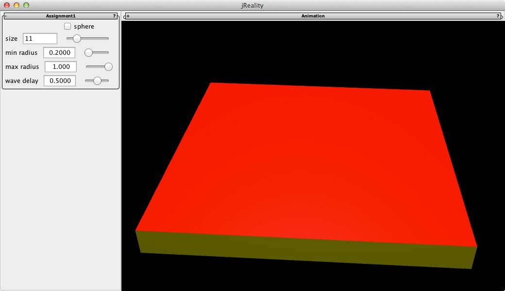
    10. Open up the course project and find the Java file src/template/Assignment1.java.  Select it, right click, and select “Run as Java application”.   You should see a window that looks something like:Assignment1That concludes the installation process.

For further information about using git, see this follow-up post.

Using the git command-line interface instead:

1.

Tutorial: Student projects page

I have added a table to the web-site for our course, where each student project will be listed.  There are two completed entries for the projects which were presented last week.  There are six other entries for remaining projects.  If you don’t see your project there, it’s because you haven’t created a project file of the form ProjectLastName1LastName2 as instructed in the previous blog.  Please do that (by renaming your current project class, for example) and send me an e-mail so I can create an entry for your project too.

In order to complete the entry for your project, I will need the following information for your project.  You can provide it to me via e-mail as soon as you have it, you don´t need to wait until after your presentation.

  • A screen shot of your application at work.  Optimal size: 250×190, but any image with aspect ratio 4:3 will do.
  • A short text describing your project.  It should fit in the space shown in the table.
  • The slides of your presentation [optional].  The best form is a pdf file.

Online documentation. The above entry also contains a link to a web-start version of your application.    This is a Java technology that allows a Java application to be run anywhere on the web by downloading the necessary resources.  This is all contained in a .jnlp file — the details don’t need to concern you, I will take responsibility for generating this file. First of all, please test it out to make sure it works.

Furthermore, there are some details regarding the on-line documentation file which have to be observed when getting the webstart to work. Here’s the situation:

When you run your application in Eclipse and hit the ‘h’ key, a browser pops up and displays the on-line documentation file associated with your application (its name is returned by the getDocumentationFile() method in the class util.Assignment). (Be sure to implement this method in your project file if you haven’t already done so, or your on-line documentation won’t be found!)

However, as a webstart, it’s not possible to use this approach since the documentation files are not available as URL’s for the browser.  Instead, the documentation file can be opened in a Java browser by clicking on the small question mark on the upper right of the GUI panel to the left of the graphics panel.  This “browser” is very rudimentary and has limitations which you need to be aware of:

  • All the html files associated to your application need to be in the same package as your project class, or in a sub-package of that class.  That means, you cannot use the symbol “../” in the definition of the path of the documentation file.
  • If you include images in your html file using the <img> … </img> command, do not use the symbol “./” when specifying the position of the image file.  For example if the file is named “foo.png”, write src=”foo.png”, not src=”./foo.png”.  Furthermore, you must explicitly specify the size of the image to guarantee that it will be displayed, using the width=”” and height=”” directives.  For example, if the image is 400×300, write width=”400″ and height=”300″.


Tutorial: Project evaluation criteria

This week focus is the criteria which will be used to evaluate your project work.  Part of the evaluation will be based on the software project itself; the rest will be based on the presentation.  I’ll deal with each of these parts separately.  The assignment for next week is to write a preliminary version of the on-line documentation file for your project, as described in more detail below.  Check this into the SVN repository by Friday, Feb. 1.

Before I get to that, here are some organizational details:

  • at tomorrow’s meeting we’ll discuss the contents of this post, with reference to a couple of example applications which I will demo.  I hope to have the pleasure of seeing at least one member of each team tomorrow morning.
  • I will also pass around a sign-up sheet for another round of appointments on Monday and Tuesday of next week (January 28-29) to discuss the progress of your projects individually.
  • Finally, if you intend to present your work in February, please notify me in writing, so that we can get serious about setting up dates for these talks.

Criteria for the software.  Here there should be no big surprises, as the criteria used to evaluate the software have all been introduced during the assignments which you have turned in during the semester.  Here’s the key points.  Pay special attention to the last two, as they are perhaps a bit new, although hopefully not surprising.

  1. The project itself should be a subclass of util.Assignment.
  2. On-line documentation. The project should include a html file as in our assignments (via the method getDocumentationFile()) which includes these three sections, listed below.  Note the I expect you to check in to SVN a preliminary version of this documentation by Friday, Feb. 1!
    1. The mathematical content of your project.  This should first of all “zoom in” to the specific domain of mathematics you are handling. For example, don’t just begin by saying, “We provide an application to identify the symmetry group of a wallpaper pattern”; rather begin by briefly reviewing the theory of symmetry groups on in the euclidean plane, and discuss how the classification of wallpaper groups can be mathematically described.  You should conclude this section with a single sentence describing your application as clearly and precisely as you can.
    2. Following this mathematical introduction, your documentation should then turn to the software implementation. How did you map the mathematical content onto the software platform you used?  Briefly describe the “flow chart” of the application, describing how you have implemented the mathematical content described in the previous section.  Mention any Java classes you have written, and any external packages or classes which play important roles in your implementation.  Indicate areas where you are satisfied with the results you obtain, and also those where you would work further if you were to continue on this project.
    3. User interface.  A description of the user interface of the program, preferably with screen shots showing the GUI (graphical user interface).
  3. User interface. How easy is your application to use?  Have you designed the user interface so that the user can experience the mathematical content in as simple and direct a way as possible? Have you taken advantage of the packages we have used so far in the tutorial (jReality, discretegroup, etc.)?  For example, have you used the appearance capabilities in jReality to help communicate the content of your application (colors, rendering attributes, etc.)?  Are the GUI components clearly labeled and neatly laid out? Does the documentation match the reality?
  4. Saving/restoring state.  One aspect of a successful user experience is the abillity to continue working after restarting the application.  That means, critical parameters should be saved (restored) when the application ends (starts up).  Use the methods  storeStates(Controller c) and restoreStates(Controller c) for this purpose.  I have extended gunn.Assignment2 to use these methods to store/restore its state; consult it to see how to do this for your own application.  These properties are saved off into a special file called the properties file for the application.  To be safe, you should specify a unique properties file for your project.  To see how to do this, look into the display() method of Assignment2, specifically, the JRViewer method setPropertiesFile().  Note that you do not need to specify a path for the properties file  if it is located in the same folder as the Java class of your application.
  5. Commented code.  Your Java code will not be put under a microscope and evaluated. At this stage, it’s more important that it works than how it works.  On the other hand,  I expect a minimal level of documentation in the source files:  Each method in your Java code should have a comment preceding it which describes what it does.

Criteria for Presentation. The talks are limited to 30 minutes.    It should follow the structure described above for the on-line documentation file.  There will be 15 minutes for discussion and questions. The best preparation is to understand and be able to talk about the mathematical content, the programming decisions you made, and how you would proceed if you were to continue with the project further.

Tutorial: Writing jReality tools

Please note the following points from the Tutorial meeting yesterday (Jan. 10):

  • Your project software should be based on a Java class which is a sub-class of util.Assignment.  Please name this class Project{TeamIdentifier}.java.  For example, if I were a singleton team, I’d name my project ProjectGunn.java.  This is a change from the convention we adopted for assignments; I’ve decided it’s worth having unique names when I’m busy testing out the results and don’t want to get confused by a run history featuring 10 applications all named Project.
  • There are at least two teams which prefer to present their results at the end of the semester (meaning either the last week of classes or the week after the last week of classes). If you would like to also present your project in February please contact me to let me know.  All the other teams are then expected to be ready to present their projects during the first week of the summer semester (the week beginning April 8).  This is a hard deadline. Please plan accordingly.
  • A sign-up sheet for appointments for team meetings next Monday and Tuesday was passed around.  If your team wasn’t represented on Thursday at the tutorial, please contact me to arrange a meeting.
  • The rest of the period I discussed the jReality tool system.  Although I promised that there will be no more assignments (your project is THE assignment), I’ve gone ahead and written gunn.Assignment7 for your edification.  It is not an assignment in the traditional sense, since you are not expected to write your own version.  However, I expect you to study it and become familiar with how the tool contained in it works, since most projects involve an interactive aspect which will require that you write your own tools.  The rest of this post describes this application and the jReality tool system.

The problem statement

Up til now, we have concentrated on creating scenes for jReality, learning in the process how to use the class SceneGraphComponent to build a scene graph, Appearance to control how it is rendered, a variety of geometry factories for generating content, and a variety of utility classes for performing common tasks.  We’ve also practiced using some external packages relevant to our mathematical theme:  the discretegroup package for working with symmetry groups, and an animation package for designing and saving animated sequences.

One major area which we haven’t worked with in detail is the jReality tool system.  This s a sub-system which allows the user to interact with the running application using input devices.  This is not the place for an exhaustive treatment. Read this Wiki entry for an introduction to the tool system.

Very short description of the tool system: In order to provide a layer of abstraction between the actual hardware input devices and the tool system (in order to allow the same application to run in different environments such as a desktop and the PORTAL), the tool system is based on the notion of an input slot, which represents some kind of input device.  Slots generate input events; tools inserted into the scene graph are notified of these events depending on the positions of a) the tool in the scene graph and b) the source of the event (also typically in the scene graph).

The basic interactive tool will have some activation slots which cause the methods activate() and deactivate() to be called; while it is active, events arising from its current slots will cause its perform() method to be called.  The tool is provided with an instance of ToolContext, which contains information describing exactly where the scene graph has been picked by the user.  The most important part of the ToolContext are methods which provide the current pick results (getCurrentPick() and getCurrentPicks()), along with methods providing SceneGraphPath’s specifying where the active tool is located, and where the picked geometry is located (getRootToTool() and getRootToLocal()).

Assignment7 embodies a simple curve editor.  The user interacts with the curve via a single tool inserted into the same scene graph component containing the curve.  This virtually guarantees that it will only receive tool events involving this curve, but not for example the square background geometry). There is a single InputSlot, the left button input slot.  When the user presses the left button, the tool is activated, and when he releases it, the tool is deactivated.  If the cursor is over the curve, the activate() method does the following:

  1. If an edge has been picked, (this can be found out by the method PickResult.getPickType()) then the tool inserts a new vertex into the curve at the picked point of the edge, and turns off picking of edges for this geometry.
  2. If a vertex has been picked, the perform() method is called.

The perform() method only takes action when a vertex has been picked.  Since edge picking has been disabled, this should always be the case. It then edits the list of vertices of the curve to move the picked vertex to a new position given by the pick point (note that this is different from the coordinates of the picked vertex, since the coordinates of the pick point correspond to the point on the tiny sphere which is drawn to represent the underlying vertex.  If you want to access the actual coordinates of the picked vertex, you  can use the getIndex() method of the PickResult class to obtain the index in the vertex list of the IndexedLineSet to obtain this information.  The code contains numerous examples of how such methods can be used so I refrain from further “explaining”.

Don’t neglect to update jReality before testing out Assignment7: a small extension had to be made to the PickResult class in order to be able to locate exactly the picked segment along the curve (the method getSecondaryIndex()).

Tutorial: End of year remarks

Today’s tutorial meeting was the last of the year.  Befitting this memorable occasion, we celebrated with punch and cake after taking care of the business at hand:

Christmas decorations via the 3D printer.  This meeting had been advertised in advance as an opportunity to play around with making a 3D print.  Since Christmas is around the corner, and we have been studying point symmetry groups, I had suggested as theme making a decoration using the framework of Assignment 6.

In preparing for the tutorial I checked in a new class, util.ThickenSurfaceDemo.  This class takes a surface and thickens it and optionally perforates it (puts a hole in the middle of each thickened polygon).  In order to work with discrete groups, I had to also add a menu item to the jReality export menu, to output a single IndexedFaceSet representing the tessellated geometry.  I managed to to do this also, but the results were not satisfactory.  The thicken step uses the vertex normal direction to thicken the surface and something was wrong the in the geometry which was being written out.  I’ve now found and corrected that bug.  So, if you have created an interesting spherical tessellation which you’d like to print on the 3D printer, here’s what you need to do:

  1. In the program in which you generate the tessellation (for example, Assignment6) save the scene with the File->Export->OBJ menu option.
  2. Start up the program util.ThickenSurfaceDemoLoad the file you created in the previous step using the menu item File->Examples->Load…
  3. Play with the parameters provided until you are satisfied.  Then to save the result for printing in the 3D Lab, use the menu item File->Export->VRML.  In the dialog box, choose the vrml2 option, and uncheck on the other check boxes.  Also save a screen-shot of the result (File->Export->Screenshot) and send it to me as an e-mail.

Note: Due to network problems with my laptop, the changes I have made won’t be checked into the SVN for a few hours (It’s now Thursday 2 pm).

Project presentation planning.  We also discussed the scheduling for giving project presentations at the end of the semester.  Different possibilities were discussed: either directly after the end of the winter semester (in the last week of the semester or the week immediately following), or before the beginning of the spring semester.  This begins on April 7.  I will not be available before April 7.  So this would involve making presentations in the first week of summer semester.  Please consider which of these alternatives you prefer and be prepared to discuss them in our first meeting after we return from the Christmas holidays.

Tutorial: Choosing a project

Please remember that your team should submit a short description of your planned project to me via email by Tuesday 11.12.12. This description should clearly state not only the content of the project, but also what form the project will take.  It is expected that every team will produce either an interactive application or animations in digital format.  These products should include documentation for the intended user/audience. In no particular order, here are some ideas for semester projects.

  1. Dynamical systems on orbifolds.  This is a big field, with many possible specific projects. Idea is to take some dynamical system defined on $\mathbb{R}^2$ (or $\mathbb{R}^3$ or $\mathbf{S}^2$ or $\mathbf{H}^2$ or …) and figure out how to map it onto some or any orbifold that belongs to this covering space.  Example: vector fields , differential equations, difference equations, cellular automata (as in Assignment1).  (To see how to integrate ODE’s in Java, see the example util.ODEExample.)
  2. Complex functions.   There are doubly-periodic complex functions, aka elliptic functions.   These can be considered functions on the torus.  Interpret them for example as vector fields, calculate the integral curves.
  3. Geometry processing on orbifolds.  For example, develop software to work with triangulations of an orbifold.  How to insert new points, how to perform geometric processing on the resulting triangulations.  Calculate subdivision surfaces in 2D- and 3D-orbifolds.  Develop tools to study embeddings of graphs on tori and higher-genus surfaces.
  4. Software improvement. Improve or extend an existing application such as TriangleGroup, Wallpaper, Maniview.  For example:
    1. Provide a geometric representation for 3D isometries so that one can provide a picture of the generators of the discrete group. This has been begun in the euclidean case (in maniview) but not completed.
    2. Better painting tool. The painting tool in the wallpaper application could be better. It would be nice for example to fair the input path of the mouse — this means approximate the path with a Bezier curve, as the user draws.  This will provide a more uniform, smoother curve, which is also easier to store off and later edit.  (Of course the user can choose whether he wants to fair or not.)
  5. Software applications. Here are some ideas for self-contained applications.
    1. 3D Kaleidoscope. Implement a general 3D Kaleidoscope in the sides of an appropriate 3D tetrahedron (one with dihedral angles which are fractions of 2Pi).  Equip this kaleidoscope with a set of built-in “worlds”, each of which generates its own regular 3D tessellation.  For example, with the same *236 kaleidoscope it’s possible to generate tessellations consisting of regular hexagons, regular triangles, or a combination of both.  Figure out how to design these worlds so that you can see through them to perceive the complete tessellation. This idea is the analogy in 3D to the TriangleGroup webstart in 2D.
    2. Designing large public sculptures with spherical symmetry.  Here the model is George Hart’s construction projects based on a single tile, typically working with the symmetry group 235.  The project here would consist of an application to allow the user to design a single tile (piece of cardboard or plywood) which is so designed that it can be easily attached to other copies either via gluing tabs or thin slots.  Given a suggest shape, the application should allow the user to move, scale and rotate it into place; and additionally provide some support for editing it in a 2D editor and updating the complete 3D sculpture in a separate window.
    3. Brick patterns. Develop a module for the wallpaper application (above) devoted to symmetry patterns based on bricks (rectangles with 2:1 aspect ratio).  See the book by Peter Stephens, Regular Patterns, (in the math library “Semesterapparat”) for examples of such patterns.  This brings one to the topic of tilings, which we haven’t explicitly studied.  There may be several distinct tilings which all have the same symmetry group.  See the web page of Craig Kaplan for more on tilings.
    4. Color symmetry.  Using the book The Symmetry of Things (see below) as a guide, write an application to explore color symmetry in wallpaper groups.
  6. Implement some of the missing 3D Euclidean crystallographic groups, for example, debug the 35 irreducible ones, or begin to work on the fibered ones.  References here: original paper by Thurston, Conway, Huson, and Delgado and these slides from a talk by Huson.
  7. Content. It’s also conceivable to author content rather than software or mathematics.  That is, choose a theme and develop material to communicate this theme to others.  Here the focus is not on innovation in mathematics or software, but communication.  Think “movie” — without expecting the production of a finished movie (that’s too much work). Examples of possible themes:
    1. An interesting set of animated tessellations would fall into this category
    2.  a gallery of classical patterns from various cultures (see the book by Stephens references in 5)).
    3. The 59 stellations of the icosahedron.
    4. “The 120 Cell”
  8. For more ideas about symmetry-related project themes, see the following resources:
    1. Craig Kaplan’s web site
    2. George Hart’s web site.
    3. Vi Hart’s YouTube videos, for example this one.
    4. The book The Symmetry of Things by John Conway  (in Semesterapparat).
    5. The book Regular Patterns by Peter Stevens (in Semesterapparat).

New for 2013

  1. Tools for visualizing projective geometry.  There have been surprisingly few attempts to develop tools for visualizing projective geometry in dimensions 2 and 3.  The mathematical foundation is clear and rich, the jReality system provides excellent support for the homogeneous coordinates and projective transformations.  What remains to do is develop some ideas for how one can specify and render geometry and projectivities in a clear, intuitive fashion. For example, “the line segment AB” is not well-defined, one must distinguish somehow between the two possibilities.
    1. One simple test case for the 2D case is the “guided visualization” we have been practicing in class in which 4 triangular regions change their appearance as one of the intersections points passes through the ideal line.
    2. Another direction for work would  be to explore how far one can go in using projective transformations to represent deformations of euclidean objects — that is, take Assignment1 extra credit option and “run with it”.
    3. Another related application: one that allows the user to specify a 3D projective transformation by picking 5 points, and then applying it to a grid of cubes (or some other regular euclidean pattern) to obtain a linear deformation of this pattern.

Tutorial Assignment 6: animating tessellations, Part II

After reviewing the results of Assignment4, I’ve come to the conclusion that we need to continue to work on this theme, since the ideas and tools which it contains are central to this course, and I have the impression that most teams didn’t really find a way to engage with the assignment. If (and only if) your team has already discussed with me and received approval for your plan for your project, Assignment6 is optional.

Therefore, there is a new assignment, Assignment6, which continues the work begun in Assignment4.  Before beginning with it, be sure to update the jreality project — there are a couple of minor changes.

Here are the main differences between Assignment6 and Assignment4:

    1. Rotation group 235. The group used is the rotation group 235, not the mirror group *235.  The fundamental domain consists of two of the 235 triangles; more importantly, the shape of the fundamental domain is more flexible and makes the process of animation friendlier for you, the animator.  You can also use the groups 233 or 234 (just change the name of the group in the source code).  (Note: there is also a variation called Assignment6b which uses a wallpaper group instead of a point group.)
    2. AnimatedPointGroup. I have written an accessory class util.AnimatedPointGroup, which takes care of all the geometric calculations.  Assignment6 is just a wrapper around this class.  The class uses a Bezier patch mesh of order 2 to create a smooth surface as fundamental domain. The corners of the patch mesh are the corners of the fundamental domain referred to in point 1) above.  The intermediate points on the boundary of the patch can be twisted around the corner points (something not possible with a mirror group), with the single interior point can be raised and lowered using a factor (essentially the homogeneous coordinate of this point).
    3. More animation features. This example includes several further features of the animation package which was introduced in Assignment4:
      1. “Automatic” animation of a class based on the Java beans technology.  In plain English, this generates animated variables for all the get/set methods in the class that involve known animatable types (such as double, int, Color, boolean).  The class AnimatedPointGroup mentioned in 1) above, is animated in this way.  The parameters referred to there for twisting the intermediate control points and raising and lowering the center point are automatically animated in this way. Look at the display() method of Assignment6 to see how to create such an animated instance of a class.
      2. Reading animation files. Also in the display() method, notice that an animation file is read in using the method ImportExport.readInto() method. Thus, when you start the assignment up you need only hit the Play button, there is no need to set key frames using the Save and Insert buttons as in Assignment4. Use the File menu on the animation panel to access the save and load features of animation files.
      3. Notice that the animation of the geometry does not explicitly occur in the setValueAtTime() method of Assignment6, as was the case for Assignment4.  This is because the AnimatedPointGroup class has been added to the animation system separately, and the animation file which is read in (in B) above) contains key frames for the parameters for this class.  You are free to choose how to implement the animation: either “by hand” in setValueAtTime() as before, or using a helper class as here in Assignment6.
    4. The assignment for this week remains, just as it was in Assignment4, to generate an animation of the fundamental domain, in this case, of the group 235. This time however I expect you to create new geometry for each time step, not just rotate a static geometry.  The example presented in Assignment6 as it comes from the repository is just to get you started on your ideas.
    5. Alternative: Assignment6b. The class  gunn.Assignment6bcan also be used as a template for this assignment.  It uses a wallpaper group (“22X”) instead of a point group, and animates a Bezier curve instead of a Bezier surface patch. The  following image shows how a frame from the animation looks.

    1. There is now a class for generating Bezier curves from a few control points: util.BezierCurve.  It has a main() method; run it to see a simple example.
    2. In Assignment6b, the helper class util.ParametrizedBezierCurve plays the role of the AnimatedPointGroup example used above.  The former class provides the same parameters as AnimatedPointGroup  and is used for animation purposes in the same way, using the KeyFrameAnimatedBean class (see display() method of Assignment6b).
    3. The fundamental domain of “22X” has two cone points of order 2.  The Bezier curve starts at one and ends at the other.  This guarantees that the resulting copies fit together to form a $C^1$ curve. The user can control the “twist” of the curve at  each of these two points (the tangent direction), as well as the homogeneous factor attached to the interior control points (the factor slider).
    4. If you want to animate another wallpaper group, use the handout sheet to locate the default fundamental domain and “design” a Bezier curve which crosses this fundamental domain so that the copies of the curve go together to form a continuous curve.  Then change the choice of group in Assignment6b accordingly and test out the result.

Tutorial Assignment 5: painting a torus

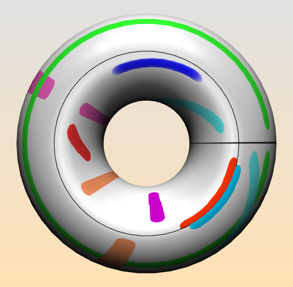
Painting a torus sounds like a simple task.  And, given an existing physical torus, it is simple. But if you want to paint a mathematical torus, represented by a model on the computer, then things get more difficult.  A glance at the image below may explain what I mean.

Quotient spaces. First recall the representation of the torus $T^2$ as a quotient of $\mathbb{R}^2$ by the discrete group $\Gamma$ generated by two independent translations; for simplicity assume unit translations in the $x$- and $y$-directions.  This group defines an equivalence relation on $\mathbb{R}^2$ according to $P \sim Q \leftrightarrow \exists ~\mathbf{g} \in \Gamma$ such that $P = \mathbf{g}(Q)$.  Then the set of equivalence classes wrt $\sim$ has a natural topology making it homeomorphic to $T^2$.

Fundamental domain. We choose a simply connected fundamental domain for  $\mathbb{R}^2/\Gamma$:  the half-open unit square $\mathbf{Q} := [0,1)\times [0,1)$. $\mathbf{Q}$ contains exactly one representative of each equivalence class.  We denote the map $\mathbb{R}^2 \rightarrow \mathbf{Q}$ which takes a point $P$ to its equivalent point in $\mathbf{Q}$ as $[P]$.  To obtain an embedded torus in $\mathbb{R}^3$,  apply an embedding map $e: Q \rightarrow \mathbb{R}^3$.  Notice that we can map any point in $\mathbf{R}^2$ onto the torus by the composition $P\rightarrow e([P])$.

Drawing line segments.  The paint program is designed to draw line segments on the torus.  By a line segment on the torus we  mean the image of a line segment $l(P,R)$ joining points $P, R \in \mathbb{R}^2$ under the map mentioned above, e([P])$.  Calling this a line segment on the torus, by the way implies that we are working with a flat euclidean torus which inherits its metric properties from the euclidean plane, not from $\mathbf{R}^3$.  That means that there are many different line segments joining the points $[P]$ and $[R]$ on the torus.

Assignment5. After this introduction, let’s turn to the actual application Assignment5, which you are now encouraged to try out. The boundaries of the original square are drawn as black curves on the torus.  A line segment is drawn starting at the point where the user presses on the mouse button and ending where he releases  it.  The line segment between the points  $P$ and $R$ is then $e(l(e^{-1}(P), e^{-1}(R))$.  The original coordinates of a point on the torus are available to the paint program as texture coordinates $(u,v) \in [0,1)\times [0,1)$.  As a result, no line segment that is drawn crosses over the black curves on the torus, since none of the pulled-backed line segments do.  Try painting yourself with Assignment5 to convince yourself that it’s impossible to draw a line segment that crosses a black curve. Part 1. In this assignment you are asked change this behavior, so that you draw a line segment which has the same end points $P$ and $R$ on the torus, but is the shortest possible such segment (or, if there are several shortest segments, draws one of these shortest segments). One approach is to consider the universal cover of the torus, $\mathbb{R}^2$. There, each point $(x,y)$ on the torus has infinitely many equivalent points $(x+n, y+m)$ for integer $(n,m)$.   Fix $P$ and let $R$ vary over its equivalent points $\{R_(n,m)\}$.  Among these points, find the one closest to $P$ and draw the line segment joining the two points using the map $P\rightarrow e([P])$.

Part 2. There is another aspect of the paint program on the torus which is not correct.  What happens when you draw a line segment very close to, and on one side of, one of the black curves?  See in the image the parallel red and blue curves in the lower right.  You see that although the end points are correct, neither curve is fully drawn: they are too thin, and end abruptly at the black boundary. This depends on the fact that the line segments are drawn as a sequence of disks.  In the simplest case, imagine a line segment of length 0 that draws a single disk.  If the center of the disk is too close to one of the black curves, then, in the current implementation, those parts of the disk which lie on the “other” side of the black boundary from the center point, will not be drawn.  The second part of the assignment is then to modify the way that the disks are drawn so that a complete disk is drawn even if the black boundary curves intersect the disk.  (This part of the assignment is harder than the first part.) You will probably need to copy Assignment5 and the class util.Paint3DTool into your own directory.  Modify Assignment5 to use the copy of Paint3DTool you have made, and modify this copy of Paint3DTool to have the behavior described above.  I have inserted some more specific hints about how to proceed into the source code, please read the comments.