Tutorial Assignment 6: animating tessellations, Part II

After reviewing the results of Assignment4, I’ve come to the conclusion that we need to continue to work on this theme, since the ideas and tools which it contains are central to this course, and I have the impression that most teams didn’t really find a way to engage with the assignment. If (and only if) your team has already discussed with me and received approval for your plan for your project, Assignment6 is optional.

Therefore, there is a new assignment, Assignment6, which continues the work begun in Assignment4.  Before beginning with it, be sure to update the jreality project — there are a couple of minor changes.

Here are the main differences between Assignment6 and Assignment4:

    1. Rotation group 235. The group used is the rotation group 235, not the mirror group *235.  The fundamental domain consists of two of the 235 triangles; more importantly, the shape of the fundamental domain is more flexible and makes the process of animation friendlier for you, the animator.  You can also use the groups 233 or 234 (just change the name of the group in the source code).  (Note: there is also a variation called Assignment6b which uses a wallpaper group instead of a point group.)
    2. AnimatedPointGroup. I have written an accessory class util.AnimatedPointGroup, which takes care of all the geometric calculations.  Assignment6 is just a wrapper around this class.  The class uses a Bezier patch mesh of order 2 to create a smooth surface as fundamental domain. The corners of the patch mesh are the corners of the fundamental domain referred to in point 1) above.  The intermediate points on the boundary of the patch can be twisted around the corner points (something not possible with a mirror group), with the single interior point can be raised and lowered using a factor (essentially the homogeneous coordinate of this point).
    3. More animation features. This example includes several further features of the animation package which was introduced in Assignment4:
      1. “Automatic” animation of a class based on the Java beans technology.  In plain English, this generates animated variables for all the get/set methods in the class that involve known animatable types (such as double, int, Color, boolean).  The class AnimatedPointGroup mentioned in 1) above, is animated in this way.  The parameters referred to there for twisting the intermediate control points and raising and lowering the center point are automatically animated in this way. Look at the display() method of Assignment6 to see how to create such an animated instance of a class.
      2. Reading animation files. Also in the display() method, notice that an animation file is read in using the method ImportExport.readInto() method. Thus, when you start the assignment up you need only hit the Play button, there is no need to set key frames using the Save and Insert buttons as in Assignment4. Use the File menu on the animation panel to access the save and load features of animation files.
      3. Notice that the animation of the geometry does not explicitly occur in the setValueAtTime() method of Assignment6, as was the case for Assignment4.  This is because the AnimatedPointGroup class has been added to the animation system separately, and the animation file which is read in (in B) above) contains key frames for the parameters for this class.  You are free to choose how to implement the animation: either “by hand” in setValueAtTime() as before, or using a helper class as here in Assignment6.
    4. The assignment for this week remains, just as it was in Assignment4, to generate an animation of the fundamental domain, in this case, of the group 235. This time however I expect you to create new geometry for each time step, not just rotate a static geometry.  The example presented in Assignment6 as it comes from the repository is just to get you started on your ideas.
    5. Alternative: Assignment6b. The class  gunn.Assignment6bcan also be used as a template for this assignment.  It uses a wallpaper group (“22X”) instead of a point group, and animates a Bezier curve instead of a Bezier surface patch. The  following image shows how a frame from the animation looks.

    1. There is now a class for generating Bezier curves from a few control points: util.BezierCurve.  It has a main() method; run it to see a simple example.
    2. In Assignment6b, the helper class util.ParametrizedBezierCurve plays the role of the AnimatedPointGroup example used above.  The former class provides the same parameters as AnimatedPointGroup  and is used for animation purposes in the same way, using the KeyFrameAnimatedBean class (see display() method of Assignment6b).
    3. The fundamental domain of “22X” has two cone points of order 2.  The Bezier curve starts at one and ends at the other.  This guarantees that the resulting copies fit together to form a $C^1$ curve. The user can control the “twist” of the curve at  each of these two points (the tangent direction), as well as the homogeneous factor attached to the interior control points (the factor slider).
    4. If you want to animate another wallpaper group, use the handout sheet to locate the default fundamental domain and “design” a Bezier curve which crosses this fundamental domain so that the copies of the curve go together to form a continuous curve.  Then change the choice of group in Assignment6b accordingly and test out the result.

Tutorial Assignment 5: painting a torus

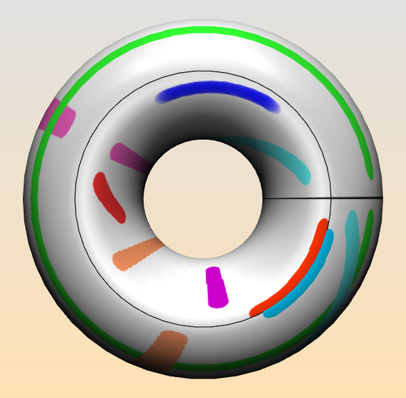
Painting a torus sounds like a simple task.  And, given an existing physical torus, it is simple. But if you want to paint a mathematical torus, represented by a model on the computer, then things get more difficult.  A glance at the image below may explain what I mean.

Quotient spaces. First recall the representation of the torus $T^2$ as a quotient of $\mathbb{R}^2$ by the discrete group $\Gamma$ generated by two independent translations; for simplicity assume unit translations in the $x$- and $y$-directions.  This group defines an equivalence relation on $\mathbb{R}^2$ according to $P \sim Q \leftrightarrow \exists ~\mathbf{g} \in \Gamma$ such that $P = \mathbf{g}(Q)$.  Then the set of equivalence classes wrt $\sim$ has a natural topology making it homeomorphic to $T^2$.

Fundamental domain. We choose a simply connected fundamental domain for  $\mathbb{R}^2/\Gamma$:  the half-open unit square $\mathbf{Q} := [0,1)\times [0,1)$. $\mathbf{Q}$ contains exactly one representative of each equivalence class.  We denote the map $\mathbb{R}^2 \rightarrow \mathbf{Q}$ which takes a point $P$ to its equivalent point in $\mathbf{Q}$ as $[P]$.  To obtain an embedded torus in $\mathbb{R}^3$,  apply an embedding map $e: Q \rightarrow \mathbb{R}^3$.  Notice that we can map any point in $\mathbf{R}^2$ onto the torus by the composition $P\rightarrow e([P])$.

Drawing line segments.  The paint program is designed to draw line segments on the torus.  By a line segment on the torus we  mean the image of a line segment $l(P,R)$ joining points $P, R \in \mathbb{R}^2$ under the map mentioned above, e([P])$.  Calling this a line segment on the torus, by the way implies that we are working with a flat euclidean torus which inherits its metric properties from the euclidean plane, not from $\mathbf{R}^3$.  That means that there are many different line segments joining the points $[P]$ and $[R]$ on the torus.

Assignment5. After this introduction, let’s turn to the actual application Assignment5, which you are now encouraged to try out. The boundaries of the original square are drawn as black curves on the torus.  A line segment is drawn starting at the point where the user presses on the mouse button and ending where he releases  it.  The line segment between the points  $P$ and $R$ is then $e(l(e^{-1}(P), e^{-1}(R))$.  The original coordinates of a point on the torus are available to the paint program as texture coordinates $(u,v) \in [0,1)\times [0,1)$.  As a result, no line segment that is drawn crosses over the black curves on the torus, since none of the pulled-backed line segments do.  Try painting yourself with Assignment5 to convince yourself that it’s impossible to draw a line segment that crosses a black curve. Part 1. In this assignment you are asked change this behavior, so that you draw a line segment which has the same end points $P$ and $R$ on the torus, but is the shortest possible such segment (or, if there are several shortest segments, draws one of these shortest segments). One approach is to consider the universal cover of the torus, $\mathbb{R}^2$. There, each point $(x,y)$ on the torus has infinitely many equivalent points $(x+n, y+m)$ for integer $(n,m)$.   Fix $P$ and let $R$ vary over its equivalent points $\{R_(n,m)\}$.  Among these points, find the one closest to $P$ and draw the line segment joining the two points using the map $P\rightarrow e([P])$.

Part 2. There is another aspect of the paint program on the torus which is not correct.  What happens when you draw a line segment very close to, and on one side of, one of the black curves?  See in the image the parallel red and blue curves in the lower right.  You see that although the end points are correct, neither curve is fully drawn: they are too thin, and end abruptly at the black boundary. This depends on the fact that the line segments are drawn as a sequence of disks.  In the simplest case, imagine a line segment of length 0 that draws a single disk.  If the center of the disk is too close to one of the black curves, then, in the current implementation, those parts of the disk which lie on the “other” side of the black boundary from the center point, will not be drawn.  The second part of the assignment is then to modify the way that the disks are drawn so that a complete disk is drawn even if the black boundary curves intersect the disk.  (This part of the assignment is harder than the first part.) You will probably need to copy Assignment5 and the class util.Paint3DTool into your own directory.  Modify Assignment5 to use the copy of Paint3DTool you have made, and modify this copy of Paint3DTool to have the behavior described above.  I have inserted some more specific hints about how to proceed into the source code, please read the comments.

Tutorial Assignment 4: using the discretegroup package

I have noticed that several of the remaining groups have checked in Assignment3, just in time to make the deadline I set for today.  Good going!  Please contact me if you still have questions regarding this assignment. Also, please check out the lecture notes on the blog  if you haven’t already.  We are collecting a complete record of the lectures.  Thanks for all who are participating.

This week’s assignment provides an introduction to the Java package I introduced on Tuesday for discrete groups: de.jtem.discretegroup.  Here’s what’s to be done:

  1. Update the jreality and the WS12 SVN repositories.
  2. Run Assignment4 and look at the code.  You’ll notice that it instantiates an instance of the spherical triangle group *235. It also uses the class DiscreteGroupSceneGraphRepresentation to get a jReality scene graph representing this group (freeing you from the kind of work you had to do in Assignment3!), and sets the fundamental domain (via the method setWorldNode()) for this scene graph to be a triangle provided by the TriangleGroup class via a static method.  Notice that dragging over the resulting shape translates the individual tirangles so they no longer line up with their neighbors.  Make sure you understand why this is so.  To rotate the complete shape, drag over the background.
  3. You should be able to explore the source code of the discretegroup package.  For example, select the text class name TriangleGroup in the source file and select on the context menu the item “Open Declaration…” This should open the source file for the class.
  4. If you prefer to have the discretegroup package as an SVN repository to check out, it’s available at the repository http://fs.math.tu-berlin.de:8000/svn/jtem/ and its project name is discretegroup.  Login as “guest” with no password.
  5. The assignment is two-fold:
  6. First, replace the given geometry (the 235 triangle) with a SceneGraphComponent of your own design that creates a more interesting shape.
  7. Second, implement the new method setValueAtTime() to change the scene graph according to a time parameter d, which should be thought of as running from 0 to 1. In order to test our your animation, follow these steps:
    1. Activate the animation panel by selecting the menu item Window->Top slot.  You should see a window looking like this:
    2. You can drag this window out of the graphics window by grabbing its title bar (recommended). Then, click once on the Save button and once on the insert button.  This sets key frames at time 0 and at time 1.  Then, you can playback the animation by clicking on the Play button.  You should see the polyhedron change from red to blue while the edges go in the other direction, color-wise.  A collage of images created by this method is shown on the new header image for the blog.  (You can animate the scene graph transfomrations also by selecting a key frame, rotating the shape, and clicking the Save button in the animation panel.)
    3.  To speed up or slow down the animation, use the slider labeled playback speed.
    4. In this way you can test out your own animations.
  8. So, to sum up, the assignment is to design an animation of the symmetry group *235 following the steps described above. Viel Spaß beim Schaffen!

Lecture Notes 5.11. and 6.11.2012

The euclidean plane isometry  consists of 5 motions:

  • Identity
  • Reflection
  • Rotation
  • Translation
  • Glide Reflection

Suppose $G<E_2$ is a discrete group. First consider the translation subgroup of $G$. It holds $G\cap \mathbb{R}^2 < E_2$. We have

  • $E_2 = \mathbb{R}^2 \rtimes O_2 $.
  • $E_2 \overset{\varphi}{\longrightarrow} O_2$.
  • $ker(\varphi) = \mathbb{R}^2 = $Translations.
  • $ker(\varphi|_G)= G \cap \mathbb{R}^2$.

The discrete translation group forms a lattice of dimension $k= 0,1,2$.

$k=1:$       There are no translations in $G$. This implies that $G$ has a fixed point ($G$ has no glides). Thus $G<O_2$ is a finite subgroup $G=C_n$ or $D_n$ for some $n=1,2,3$. As groups of symmetries in $\mathbb{E}^2$ these are called the rosette groups or point groups since they leave at least one point fixed.

$G=C_n$ are called the cyclic group.                                                                                   

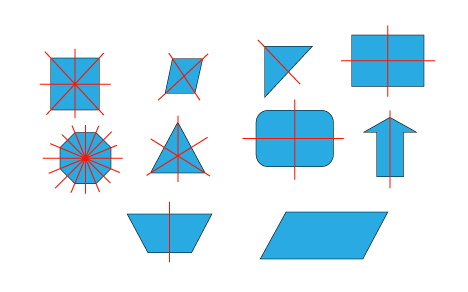
The cup (first object) is $C_2$ since it has a $180^°$ symmetry. The recycling logo (2nd object) is $C_3$ and the star (3rd object) $C_5$ since the they are $120^°$ and $72^°$ symmetric. The group $C_1$ has no symmetry and can be represented by an or an R.

$G=D_n$ are called the dihedral group.

Starting with the upper left the square is $D_4$, the rhombus is $D_2$ the triangle $D_1$. The dihedral group is the group of regular polygons, so an n-gon is $D_n$.

$k=1:$ These groups are called the frieze groups. They have the following definition:

$G\cap \mathbb{R}^2 = \{ \tau_{nv} : v\neq 0 \in \mathbb{R}^2, n\in\mathbb{Z} \} = \langle \tau_v\rangle\cong \mathbb{Z}$.

 $k=2:$ These groups are called the wallpaper groups. They have the following definition:

$G\cap \mathbb{R}^2 = \langle \tau_v, \tau_w\rangle \{ \tau_{nv+mw} : v,w\neq 0 \in \mathbb{R}^2,  n,m\in\mathbb{Z} \} \cong \mathbb{Z}^2$.

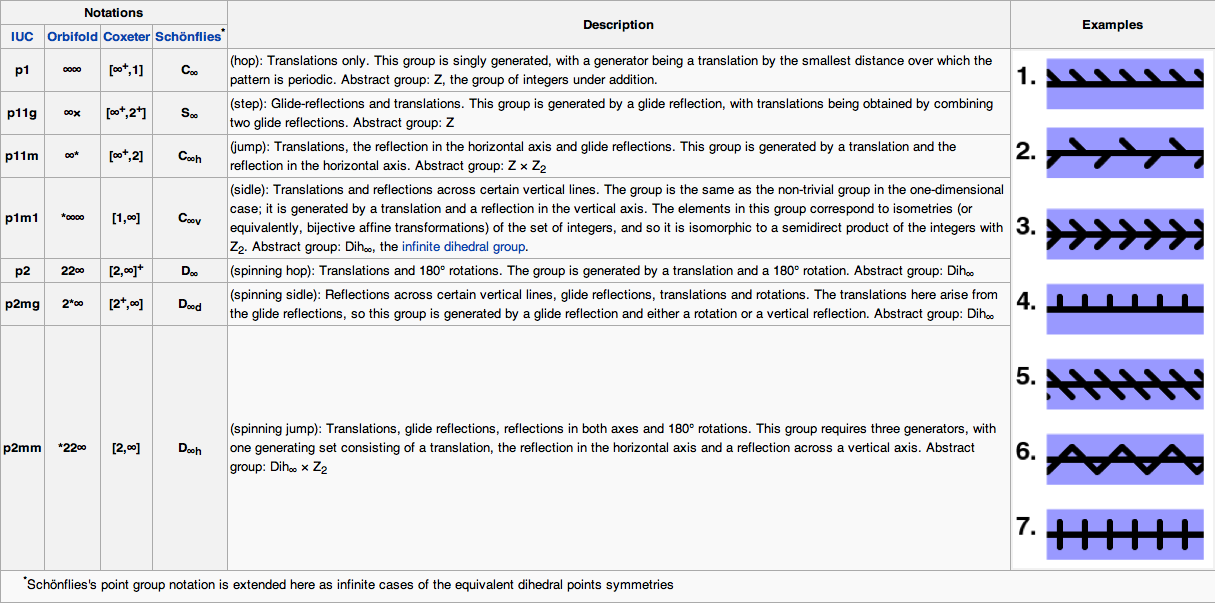
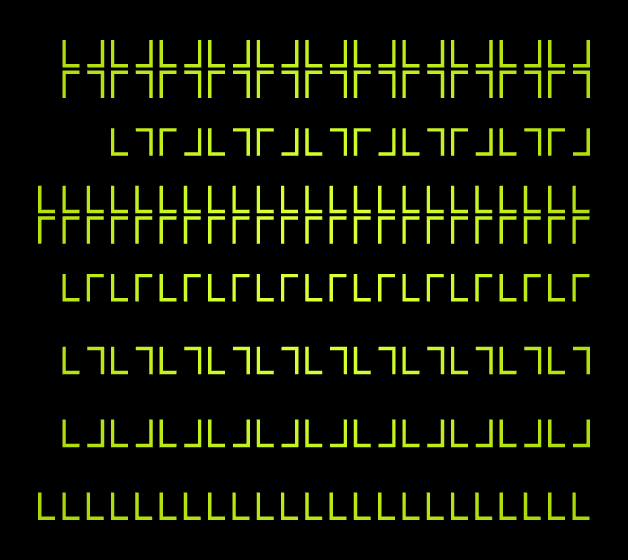
 There are seven distinct subgroups (up to scaling and shifting of patterns) in the discrete frieze group generated by a translation, reflection (along the same axis) and a 180° rotation. An overview gives the following picture 

The Orbifold notation was the name we used in the lecture.

Take a width-$n$ strip $[0,n]\times\mathbb{R}\subset\mathbb{R}$ and glue its edges to give a cylinder. Any of our seven groups will give a group symmetry of the cylinder with exactly $n$-fold rotation around vertical axis. This gives $7$ families of symmetry groups, indexed by $n$. These are finite subgroups of $O_3$. They are exactly the ones that preserve the equator (or equivalent preserve the poles). These are called the axial groups:

  • $nn$, rotations (abstr: $\mathbb{Z}_n$)
  • $nx$, rotary directions (abstr: $\mathbb{Z}_{2n}$)
  • $n*$, (abstr: $\mathbb{Z}_n \times \mathbb{Z}_2$)
  • $*nn$, (abstr: $D_n$)
  • $22n$, (abstr: $D_n$)
  • $2*n$, (abstr: $D_{2n}$)
  • $*22n$,  ($D_n \times \mathbb{Z}_2$)

Special cases for $n=2$:

  • $22$, a 2-fold rotation (abstr: $\mathbb{Z}_2$)
  • $2X$, a 4-fold rotary reflection (abstr: $\mathbb{Z}_4$)
  • $2*$, rotation, mirror, and antipodal map (abstr: $\mathbb{Z}_2^2$)
  • $*22$, 2 mirrors which yield a rotation (abstr: $\mathbb{Z}_2^2$)
  • $222$, rotations (abstr: $\mathbb{Z}_2^2$), the Klein-4-group
  • $2*2$, rotation and mirror, (abstr: $D_4$)
  • $*222$ only reflections, (abstr: $\mathbb{Z}_2^3$)

Note that the abstract groups sometimes look different as, e.g., for the group $222$, which should have $D_2$ as its abstract group instead of $\mathbb{Z}_2$. These are equivalent because

$D_{2}  \cong D_1 \times \mathbb{Z}_2 \cong \mathbb{Z}_2$.

In general, for odd $m \in \mathbb{N}$, it holds

$D_{2m} \cong D_{m} \times \mathbb{Z}_2$, and $\mathbb{Z}_{2m} \cong \mathbb{Z}_m \times \mathbb{Z}_2$.

For $n=1$, only three different groups remain:

  • $11 = 1$, the trivial group
  • $1x = x$, identity and antipodal map (abstr: $\mathbb{Z}_2$)
  • $1* = * = *11$, a single mirror, (abstr: $\mathbb{Z}_2$)

Of course, there are more discrete subgroups of $O_3$. Most of them correspond to the symmetry groups of the platonic solids. First, we give the theorem:

Theorem: The finite subgroups of $O_3$ are the 7 families of axial groups and the 7 platonic symmetry groups $*235$, $235$ (symmetries of icosahedron and its dual, the dodecahedron), $*234$, $234$ (symmetries of the cube and the dodecahedron), $*233$, $233$ (tetrahedron), and $3*2$ (the so-called pyritohedral symmetry).

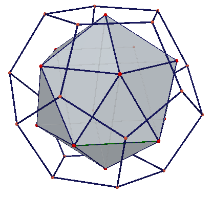
The figure on the left shows the icosahedron inside of a dodecahedron. Recall that the dual or reciprocal of a solid evolves from faces becoming vertices, roughly speaking. A symmetry of one solid is also a symmetry of its dual.

The symmetry group is $*235$, which has the rotation part $235$ as subgroup.  (http://apollonius.math.nthu.edu.tw/d1/dg-07-exe/943251/dynamic/duality.htm)

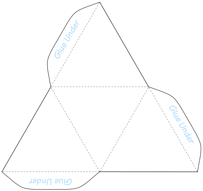
The tetrahedron has the symmetry group $*233$, with rotation subgroup $233$.

You can easily make a tetrahedron yourself by using the figure to the right, and search for the symmetry groups yourself.

Note that the tetrahedron is dual to itself.


The cube and its dual counterpart, the octahedron, have the symmetry group $*234$, and $234$. The last symmetry group, the pyritohedral symmetry group, comes as the intersection of the octahedral and the dodecahedral symmetry groups,

$3*2 = *235 \cap *234$.

In the figure below, you see a pyritohedron, which is not platonic (note that the faces are irregular pentagons).

Wallpaper groups

Back to $E_2$ (the euclidean motions in the plane), the discrete subgroups which have a translational part of dimension 2 are called wallpaper groups. In the figure below, you find an exhaustive list of the 17 wallpaper groups, each with its fundamental domain, and generating symmetries.

The 17 wallpaper groups

Tutorial Assignment 3: Frieze Groups

Before proceeding to the assignment, this news: The wallpaper group demo program is running again (there were some problems in the past few days with reorganization of the jReality website). Also, to change groups use the submenu Wallpaper->Groups... If you get tired of painting, try the automatic option Wallpaper->Run (Wallpaper->Pause to stop).

In this assignment you are asked to familiarize yourself with frieze groups, introduced in the  lectures this week.  A Euclidean frieze group is a discrete group of motions of the plane  that has exactly one independent translation.  There are seven such groups (up to affine conjugacy).

Directions for Assignment 3

  1. Update from the SVN repository. Run the application gunn.Application3. Use the ‘h’ key to browse the on-line documentation.  Note that the inspector panel has a combo box with the names of the 7 frieze groups. Your task is to activate this combo box, so that choosing a frieze group generates a pattern with the symmetries of the chosen group.
  2. Copy gunn.Assignment3 into your own package.  Modify it in order to implement as many of the frieze groups as you can.  The method updateCopies() has been prepared for this modification. This picture shows how these groups appear using the same ‘L’ motif as that in Assignment3: The seven frieze groups
  3. Creating the isometries. To help you generate the correct isometries, I have added a new class util.IsometryExamples.  Run it and see that it displays isometries of the types needed for the frieze groups: translations, rotations of 180 degrees, reflections in horizontal and vertical lines, and glide reflections.  Study the code to see how that is done.  Notice that we are working the euclidean plane but the matrices are calculated in euclidean space, such that the z-coordinate is left unchanged.  A reflection in a line in the (x,y) plane is specified as a reflection in the plane in 3-space containing the line and perpendicular to the (x,y) plane, etc.
  4. Strategy hint.  Notice that all the groups above have translational subgroups, such that there are either 1, 2, or 4 conjugacy classes with respect to this translational subgroup. By adapting the existing translation code to implement the translational subgroup (which means, in general, using a translation either 2 or 4 times as long), one is left with the task of generating 1, 2, or 4 group elements to represent the conjugacy classes, and putting them into a single SceneGraphComponent where they can be acted on by the translation subgroup.
  5. Non-euclidean metrics. It is possible to extend the definition of frieze group to be valid also for the elliptic and hyperbolic plane, since the both cases the notion of one independent translation is valid. It is optional whether you maintain the non-euclidean metrics in your modified version.  I encourage you to attempt to do so, since all the operations are well-defined also in the non-euclidean metrics.  As we have seen, the MatrixBuilder class supports construction of isometries in all three metrics. If you follow the strategy hint above, the simplest (metric-neutral) way to find a generator of translation subgroup is probably to calculate the appropriate power of the original translation.
  6. Fundamental domain.  Find the reference to the field fundamentalDomain in the method initCopies().  This node holds all the geometry contained in the displayed pattern, i. e., the frieze group acting on this SceneGraphComponent generates the pattern. This currently contains the single child representing the letter ‘L’.  Create a SceneGraphComponent and fill it with geometry describing a pattern of your choosing, and add it to the fundamentalDomain instead of, or in addition to, elSGC.
  7. Painting tool. [Optional] Create a single polygon of the appropriate size and shape and attach it to fundamentalDomain. (For example, use the method Primitives.texturedQuadrilateral() to generate such a shape).  Then, adapt the 3D painting tutorial example de.jreality.tutorial.tool.Paint3DToolExample to  create a tool which you add to the scene graph using fundamentalDomain.addTool(). This tool will allow you paint a pattern on this geometry and have it instantly replicated over all the copies.  Once you have a pattern you like, save it (using File->Export…->Image with size 1000 x 288) and I will add it to the cycling images used for the header of the blog.

Tutorial: Development tips and tricks

[Note: Go here for Assignment 2.] In this post I want to collect some miscellaneous tips and tricks related to the nitty-gritty of our programming environment for this course.  Please feel free to post other related helpful hints as comments to this post! I’ll be adding entries throughout the semester so it might be good to bookmark this page. I’ll add new entries at the top.

  1. Animating a scene graph.  For best results, re-use SceneGraphComponents and geometry factories.  For example, if only the geometry is animated, you can simply call the factory.set…() methods you need, then call update().  The geometry will be changed and the scene graph re-rendered without further work.
  2. html on-line documentation: Please try to reduce the size of your html folders in the SVN repository.  Large files make the update process with SVN slow and unreliable.  Please try to keep the total under 1MByte per team.
  3. Using the computers in MA 316: Our first Thursday in this lab, it was difficult to login successfully to these machines.  I’ve found out the problem. To use these computers, you have to select a session type on the pull-down menu below the login field. KD3 or Gnome are common choices, if you don’t already have a favorite (apparently KD4 is not available, which is the source of the problem); if you’re just going to be running eclipse, it shouldn’t matter much which you choose as long as you can get a shell/terminal.  FYI, here are the directions again  for getting the correct eclipse version on these machines.  Execute in a shell:
    1. ln -s /net/MathVis/eclipse64-subversive/eclipse eclipse
    2. ./eclipse
  4. If your Java process runs out of heap space:   You can direct the Java Virtual Machine to allocate more space when it starts up. To allocate 2 GByte initially and as final limit use the arguments -Xms2048m -Xmx2048m.
    1. You can set this just for this application in Eclipse using the menu item Run configurations…->Arguments->VM arguments.
    2. Set it globally for all Java VM’s in eclipse using Eclipse->Preferences…->Java->Installed JRE’s->Edit->Default VM Arguments.
  5. Update SVN frequently: Make a habit of updating from the SVN repository after you start up eclipse.  Some files your application depends on may have changed; I try to avoid such changes but sometimes it can’t be helped, and it’s better to adjust to the changes sooner rather than later.
  6. Use the utility class de.jreality.geom.Rn: If you are doing calculations involving points in $E^3$ or vectors in $R^3$, consider using the static methods Rn. It’s not possible to give an exhaustive listing here of these methods, but these include adding, subtracting, cross product, multiplying by a scale, normalizing, finding the norm, distance and angles,  etc.  Many methods also act on arrays of points or vectors (type double[][]). Take a look for yourself. When using homogeneous coordinates or doing projective geometry, consult Pn, in the same package.
  7. When in doubt, consult the tutorial examples: Just because you’re writing your own programs now doesn’t mean you can’t benefit from looking back at the tutorial examples.  In fact, now that you know more what’s going in, it’s probable that you will be more appreciative of some features which previously, in the initial confusion, you didn’t fully understand.  Once more, the principle at work here is: avoid writing your own code wherever possible.  It gives you more time and energy to … write your own code.