
Let us now work on the visualization of edges and points. In case you worry that your screen looks slightly different from the pictures we show: For the pictures we already applied the White Porcelain material as explained in the next post (the difference is not large).
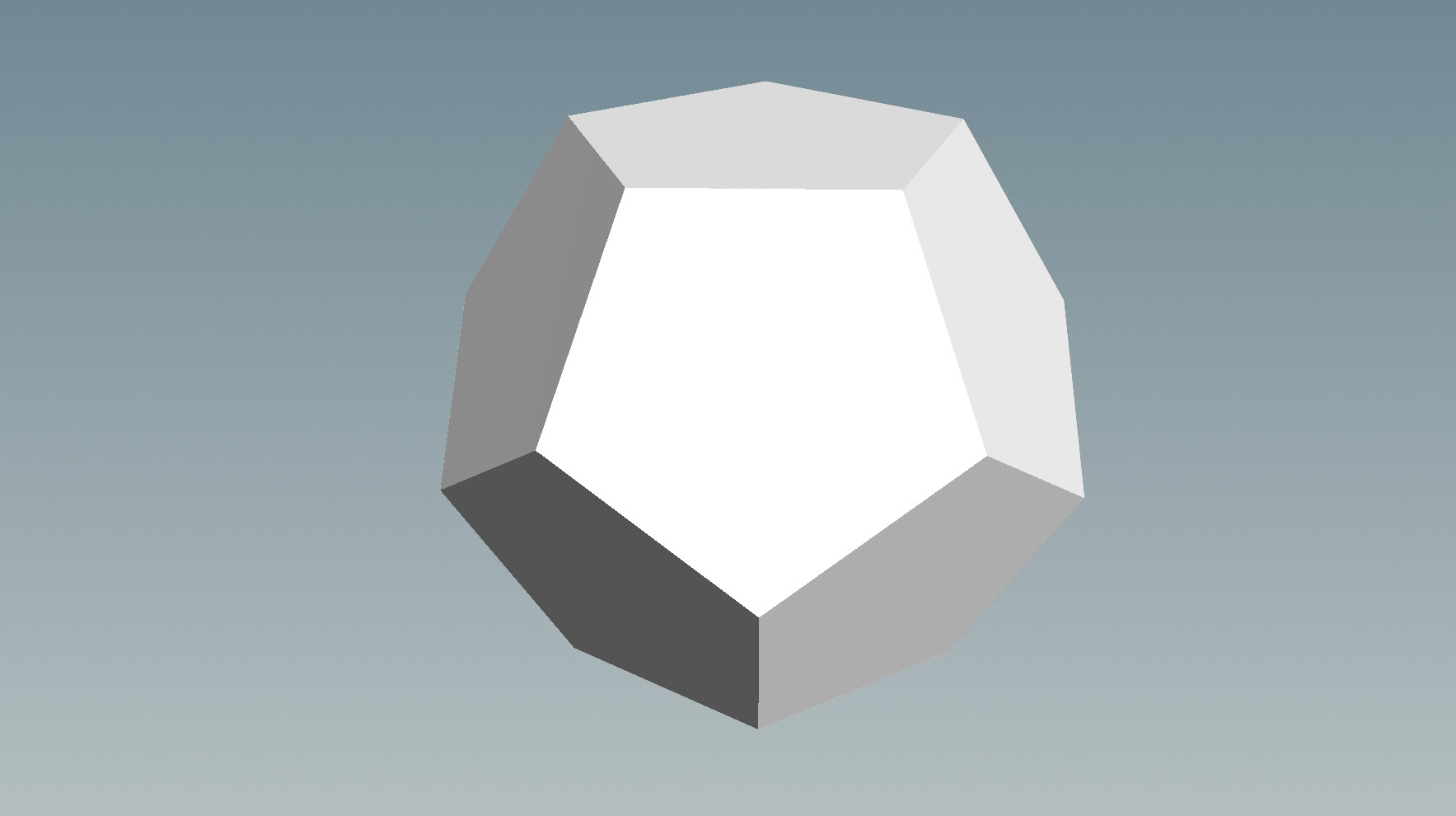
Start with a Platonic Solids node providing a dodecahedron and connect below it a Facet node as in the previous post.
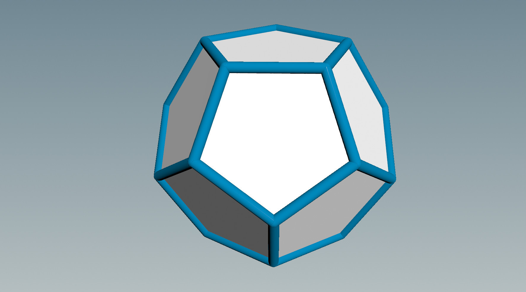
Now feed the dodecahedron into a node of type Wireframe and in the parameter interface of this node set Wire Radius to .04. Connect below Wireframe a node of type Color and choose a color you like. Use a node of type Merge (see the previous post) to display the faces and the edges together. The result will look like the picture below.
Now create a Sphere node, set the sphere radius to 0.1 and connect below it another Color node to makes the sphere red. Feed the result into the left input of a Copy node and connect the right input of this node to the output of Platonic Solids. Copy will translate a copy of the object in its left input to every point of the geometry in its right input.
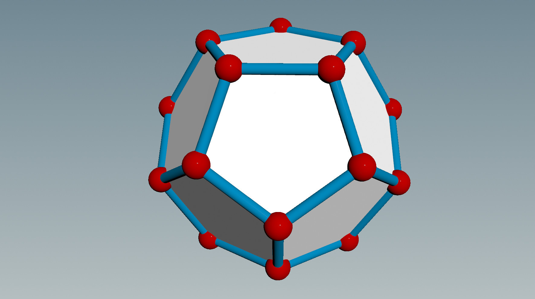
This kind of visualization is reminiscent of the ball-and-stick models used in molecular Chemistry. It is quite useful for working with coarse polyhedral geometries. Here is the final network:
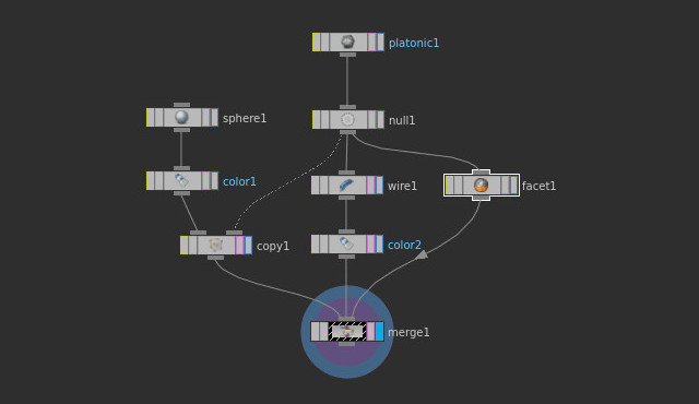
Why did we put a node of type Null below the Platonic Solids node? This is because we then can select all nodes except Platonic Solids and choose “Collapse” from the context menu (right mouse button) of the Network View. This will reduce the visual clutter of more complicated networks. Moreover, we can then save the collapsed as a so-called digital asset. In fact, if you installed the ddg asset library coming with this course, you will have this node available in the tab menu under the name Ball and Stick.